BYB User Manual Page 24 of 55 PN: 90020 Version: 1.4
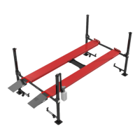
The powered runway will be installed
first, this is the upper runway that was
removed and set on blocks. Take note
to visually locate the hole for the
hydraulic fitting exiting the side of the
powered runway, this fitting must be
located next to the column the power
unit will be bolted to, front left or rear
right. Rotate the package assembly, if
needed, so the hole is pointed outward
and the accessory rail welded to the
side of the track is inward, towards the
center. Roughly align the holes in the
track with the holes in the
crossmember. Danger, these parts are
heavy, work slowly and cautiously as
they are placed.
STEP 4: Runway Installation
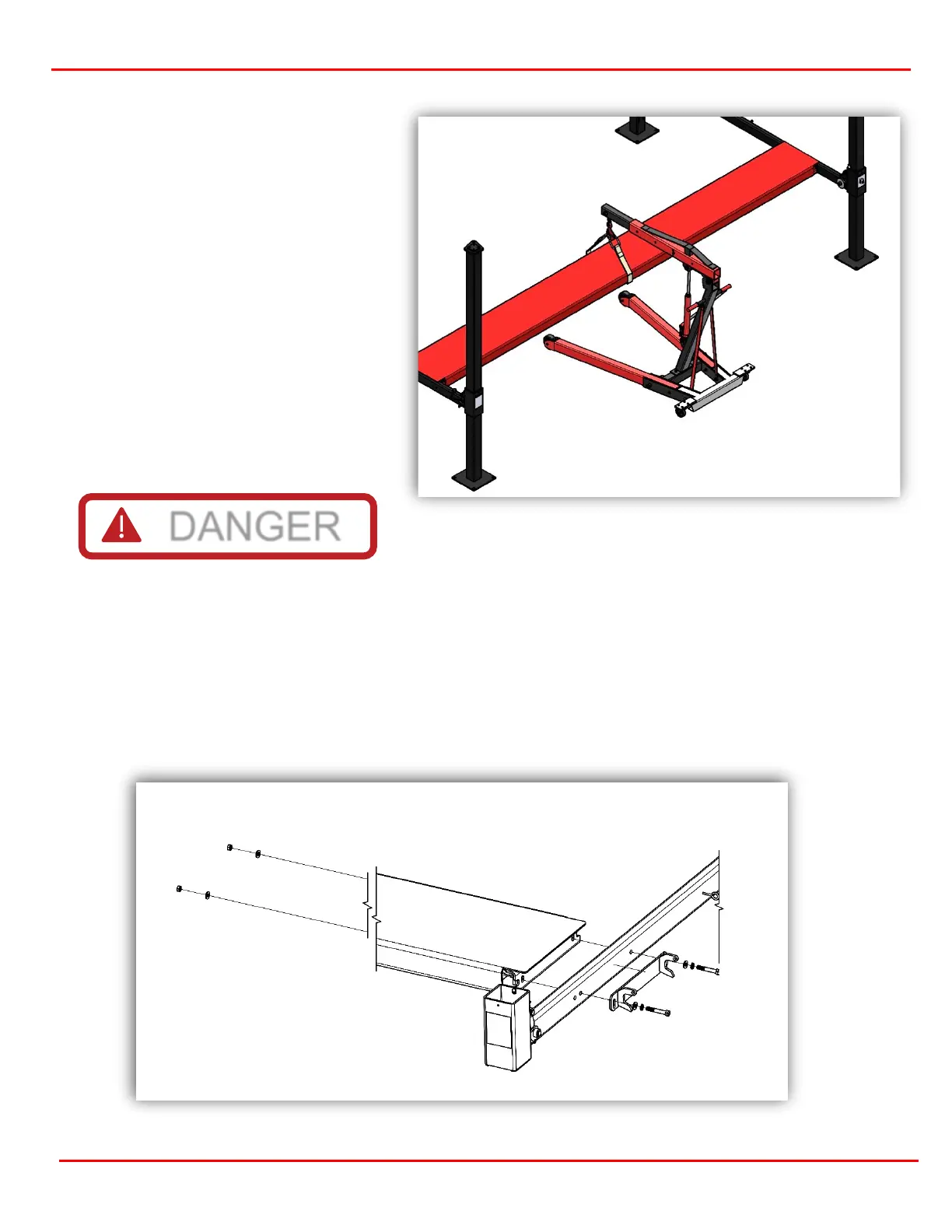
Automatic Wheel Stops
Find the automatic wheel stop mounting plates (2) and 1/2-13 x 3-1/4 bolts (4), 1/2-inch washers (8), 1/2-13
nuts (4) and 1/2-13 lock washers (4). Assemble as shown in figure 4.2. The nut and washer may be installed
by placing through the window where the cables exit the runway and held with an open-ended box wrench.
Repeat on the opposite side of the runway. Once the powered runway is secured, repeat the process for the
next runway. Ensure the accessory rails are both facing each other.
Figure 4.2