BYB User Manual Page 28 of 55 PN: 90020 Version: 1.4
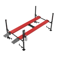
Figure 6.1 – Top Cap Orientation
STEP 6: Installing Top Caps & Power Unit Mount
There is a Top Cap for each of the four columns that secures the ends of the lift cables. The Top Cap with
the holes (used to attach the power unit arm) mounts on the leg where the hydraulic fitting exits the runway.
STEP 7: Hydraulic Hose & Drain Kit
.
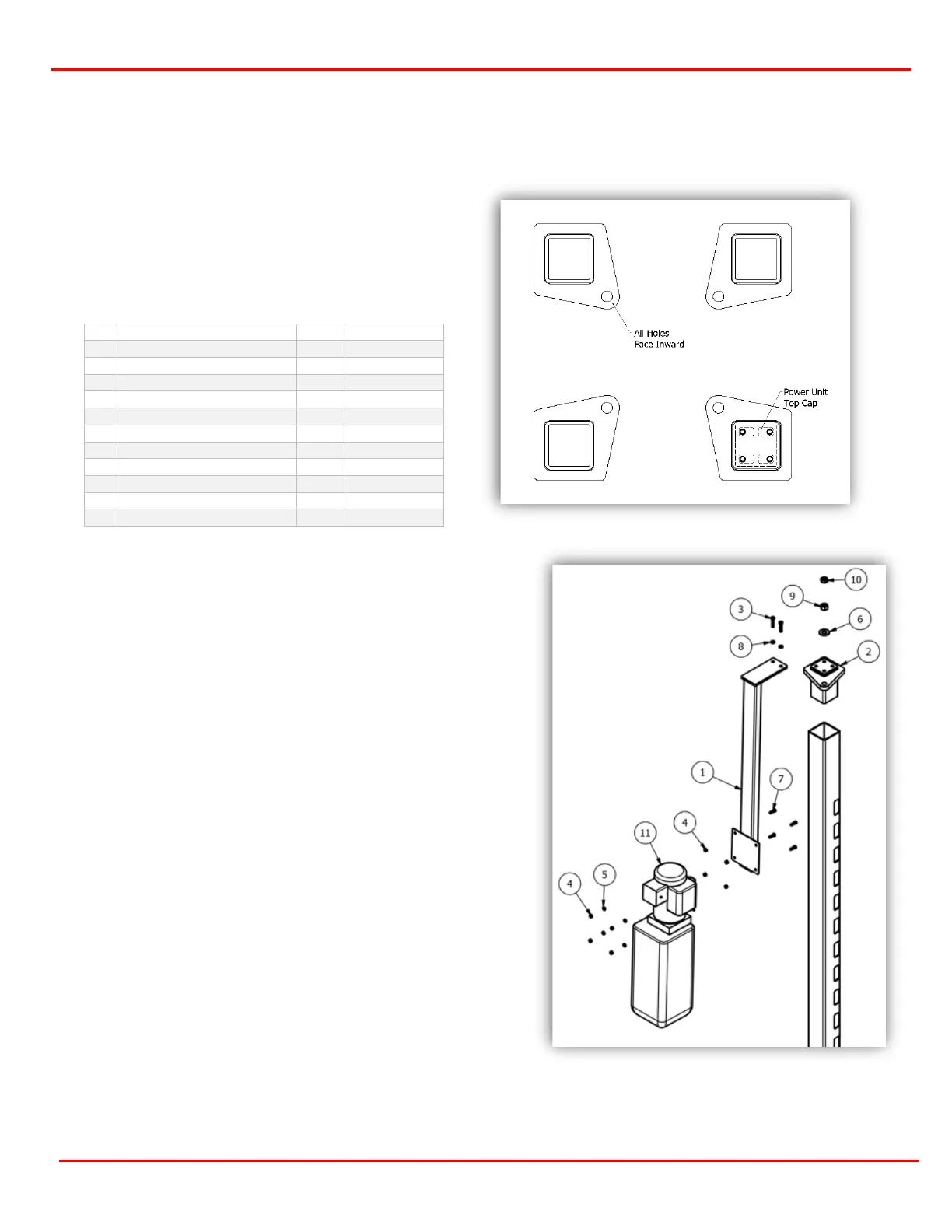
The Power Unit Mounting Bracket can be mounted in
two positions, on the outer side of the column or turned
to the inside for a narrower width profile (figure 1.1)
Select the position that favors the layout of your shop or
the desire operator position. Using (2) 3/8-16 HHCS
bolts and (2) split washers, install the power unit (Figure
6.3).
Install the power unit mount the top cap using two
OUTER MOST HOLES to provide proper clearance
between the power unit mount and leg.(Figure 11.4)`
To mount the power unit to the bracket, install the 5/16-
18 nuts and bolts first. This will allow the power unit to
hang on the bolts. Then attach with the (4) lock washers
and (4) remaining 5/16 nuts.
Figure 6.2 – Top Cap Orientation
Find the 90° bulkhead fitting (90005) attached to the
end of the hose on the cylinder runway. Remove the
packing nut and insert into the hole provided, secure
with previously removed packing nut.
Next connect the hose from the hardware box to the
bulkhead fitting. Remove the plastic shipping plug from
the base of Power Unit pump and attach the 3/8 Male
JIC-3/8 ADJ O-Ring, 90 Degree EL hydraulic fitting
(60066-01) from the hardware box to the power unit and
Orient the holes for the cables so they are pointing
inward to the inside corner of the post (figure 6.1 &
6.2).
Note that the longest flat side of the Top Cap is
flush with the outside of the column as referenced
from the front or rear (figures 6-3 & 6-4).