BYB User Manual Page 35 of 55 PN: 90020 Version: 1.4
STEP 11: First Start Up (At Installation)
Wax the outside of the columns where the UHMW Guide Blocks will make contact to the column. The wax
will reduce friction and make for smooth operation (figures 11.1 & 11.2). Grease the zerk fittings (4 on the
powered runway and 2 on each crossmember).
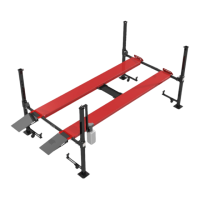
Confirm that power to the lift has been installed by a licensed electrician and is safe to operate. Press the
power switch on the Power Unit to take slack out of the cables. Once the slack is taken out, raise the lift
slightly to release the primary locks then pull the primary lock release handle. The locks should all clear the
legs by the same distance. Have your assistant walk around and check for good clearance between the
locks and columns. If not, adjust by threading in or out the 3/8-24 threaded rods attached to the hiem ends
installed in Step 5. Lower the lift by releasing the primary lock handle and pressure relief handle on the
power unit.
With the primary locks adjusted, raise the lift again by pressing the power unit’s power switch. Pay careful
attention to the crossmembers to ensure all 4 are sliding on the legs. If one corner gets bound up, STOP.
Pull the primary lock release handle and at the same time press the pressure relief handle on the Power Unit
to lower the lift to a position where the runways and crossmembers are level. Once level, wax the bound leg
and attempt to lift again.
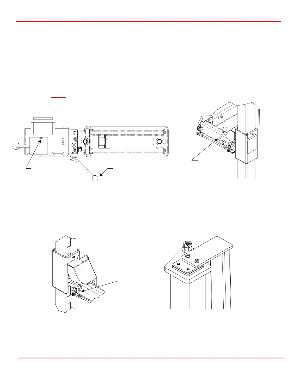
Raise the lift until the top of the highest lock cover is flush with the bottom of a lock cutout (figure 11.3).
Adjust the cables on the other three posts to raise up them so all 4 corners are equal. Adjust the cables by
tightening the cable adjusting nut on the top of each post top cap, then tighten the jam nut to the adjusting
nut to lock the cable in place (figure 11.4).
Relief Handle
Release Handle
Figure 11.1 Power Unit Features
Figure 11.2 Primary Lock Release