BYB User Manual Page 22 of 55 PN: 90020 Version: 1.4
Using wood blocks, prop the leg up so there is clearance to slide the crossmember down the legs. Position
the crossmember so the guide blocks align with both columns, adjust the leg spacing as necessary to match
them up.
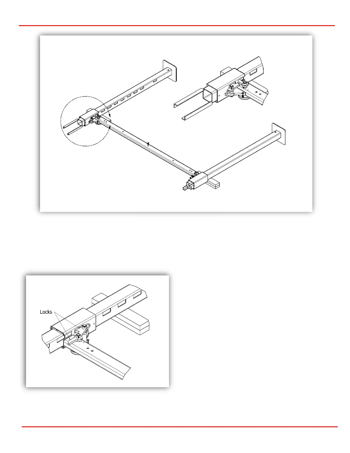
Place two glide blocks in the corners as shown in
figure 3.7. Do not install all 4 glide blocks at this
time. A dead blow hammer may be used to gently
tap in the blocks, do not force into place. Rotate the
locks as to not catch in the leg holes.
Gently slide one leg into the crossmember sleeve,
slightly wiggling if needed. Stop when around 40
inches from the foot pad or the 5th lock hole up.
This provides a good working height for installing
the runways.
Rotate the locks on the first leg to lock into position
and repeat the process for the second leg. Once
the primary locks are engaged on both legs, the
leg/crossmember assembly is ready to raise into
position.
Figure 3.8 Positioning Locks
Figure 3.7 Lifting the Crossmember