Electrical installation, cable connection, cable cover
46 / 94 DLT-V72 Series Manual V2.00 Advantech-DLoG
8.4. Connecting the USB, Ethernet and COM cables
Observe the following when connecting/removing external devices on the DLT-V72.
Only use accessories that have been tested and approved by Advantech-DLoG for the
respective DLT-V72.
The DLT-V72 may not be connected to the power supply if external devices are being
connected/removed (not applicable for USB devices)
Otherwise considerable damage could be caused to both the DLT-V72 and the peripheral
devices.
Make sure that peripherals with their own power supply are either switched on at the same
time as the DLT-V72 or after the start of the DLT-V72.
Otherwise, you must ensure that a backflow from the external device to the DLT-V72
cannot take place.
Only power up the DLT-V72 when all devices have been connected and the DLT-V72 has
been closed correctly (remember the cable cover!). Otherwise, you may damage the
DLT-V72.
Please observe the mounting instructions supplied with the optional accessory.
8.4.1. USB cable
Plug the required USB cable into the associated port.
Fold open the respective round cable passage in the rubber seal.
Insert the USB cable.
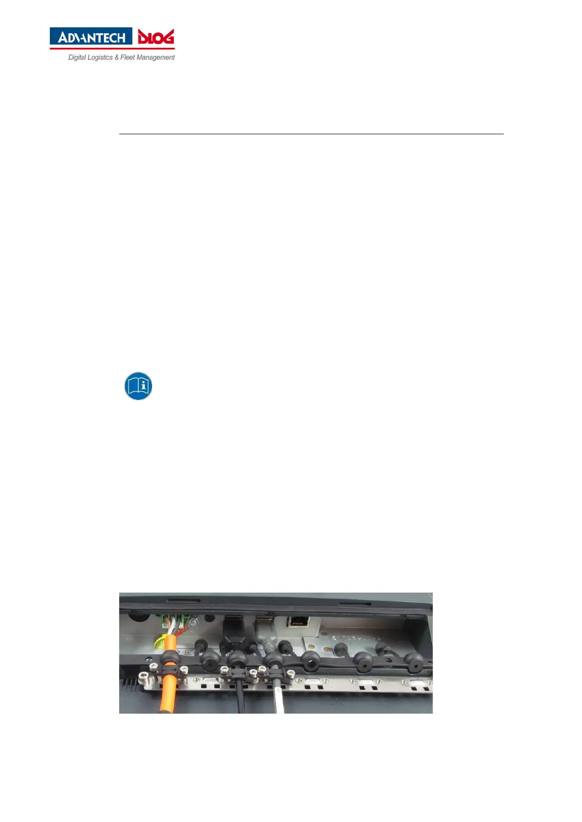
Secure each USB cables to the strain relief rail with cable clips and screws.
ATTENTION Tighten the mounting screws sufficiently but on no account pinch or crush the cable.
If you do, the cables may break or the cable insulation may get damaged.
Fig. 8.5: USB cable on the connector panel; secured to the strain relief rail