64 / 94 DLT-V72 Series Manual V2.00 Advantech-DLoG
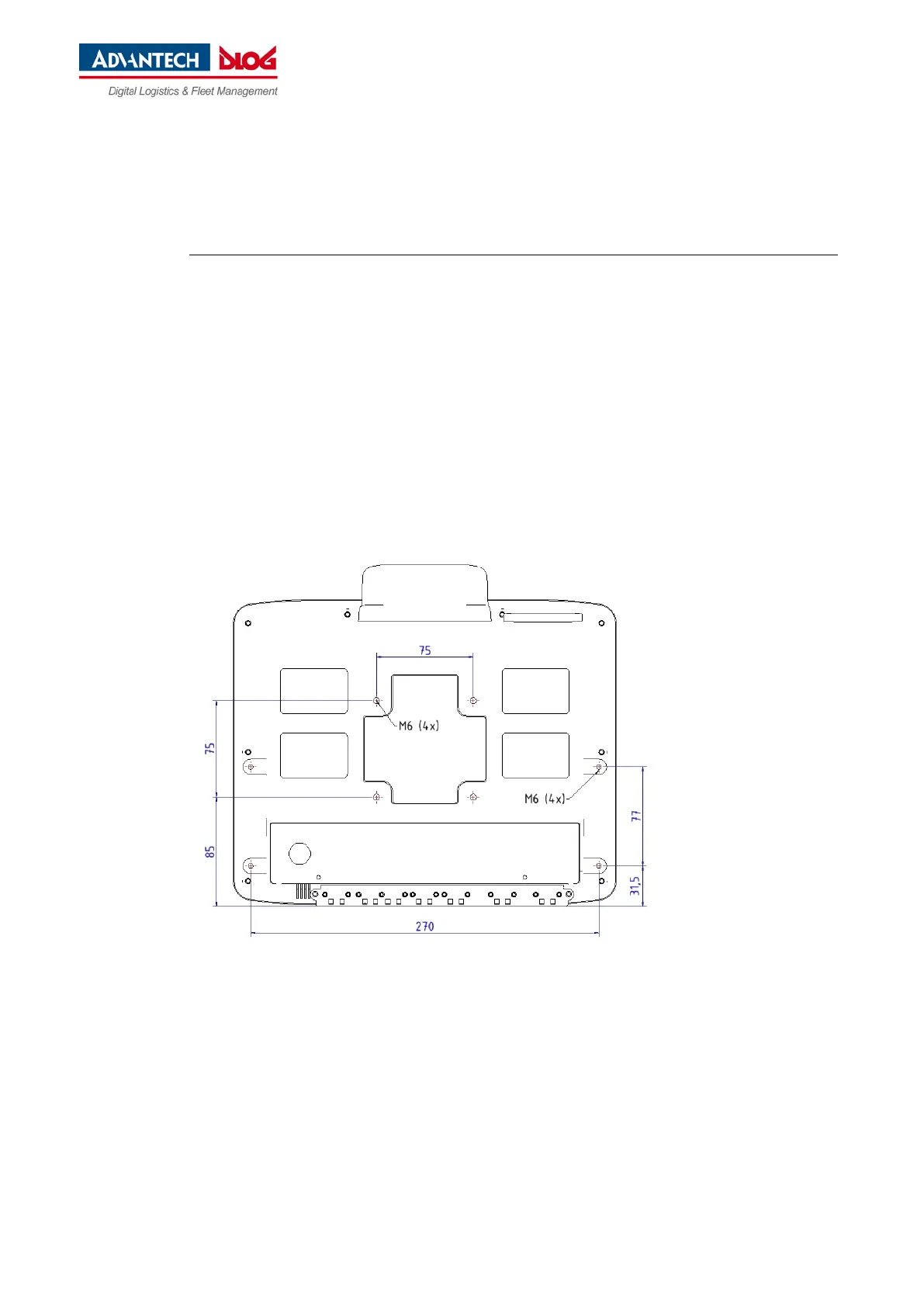
11.4. Position of VESA drill holes
The back of the DLT-V72 has a VESA-compatible 75 x 75 mm mounting hole pattern. It is used to attach
VESA-compatible mountings to mount the DLT-V72 at the deployment location.
ATTENTION: Physical damage
Only use mountings and mounting materials that have been tested and approved by ADLoG for the
respective DLT-V72. Otherwise, any DLoG GmbH warranty for this device will be void.
11.4.1. DLT-V7210
Dimensions without add-ons (in mm):
Depth of thread: M6 x 6mm.
Fig. 11.4: Position VESA drill holes DLT-V7210