AMT-70/AMT-73/AMT-75 Installation and Operation
CHAPTER 8 CABLES AND PIN-OUTS
8.1 Rear Panel Connector Arrangements
The connector arrangements for the AMT-70L and AMT-73L are provided in the following figures.
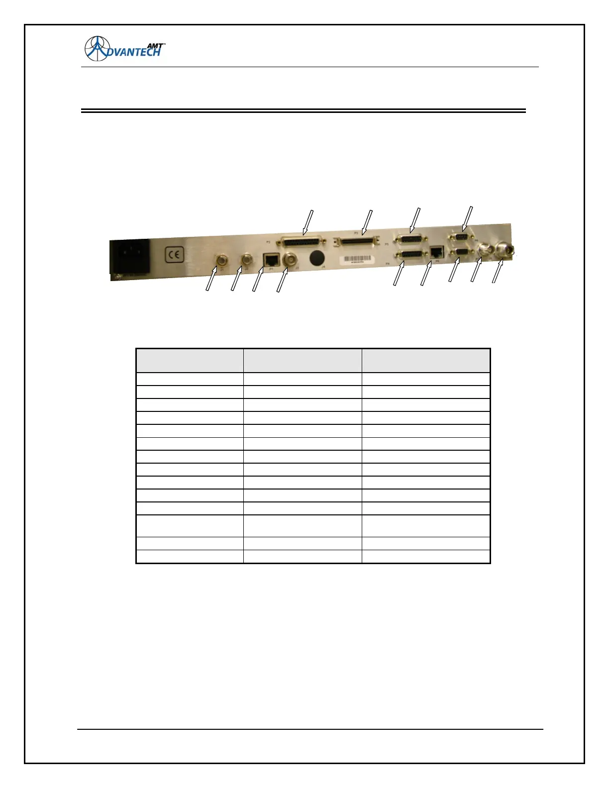
Figure 44: Back Panel Connectors for AMT-70
Back Panel
Connector Name
Description Connector Type
J1 RF IN (2) Type F (female)
J2 RF IN (1) Type F (female)
J3 ASI OUTPUT BNC (female)
J4 EXT REF BNC (female) (Optional)
J5 ASI INPUT BNC (female)
J6 MOD RF OUT Type N (female)
P1 DEMOD ETHERNET RJ-45
P2 RS-530 25-Pin D
P3 HSSI Subminiature 50-Pin male
P4 REDUNDANCY 15-PinD
P5 ALARMS 15-PinD
P6 MOD/DEMOD
ETHERNET
RJ-45
P7 RS-232 (M&C) 9-PinD
P8 RS-485 (M&C) 9-PinD
106
J1 J2 P1
P8P5
P3
J6J5P7
P6P4
J3
P2
J1 J2 P1
P8P5
P3
J6J5P7
P6P4
J3
P2