AMT-70/AMT-73/AMT-75 Installation and Operation
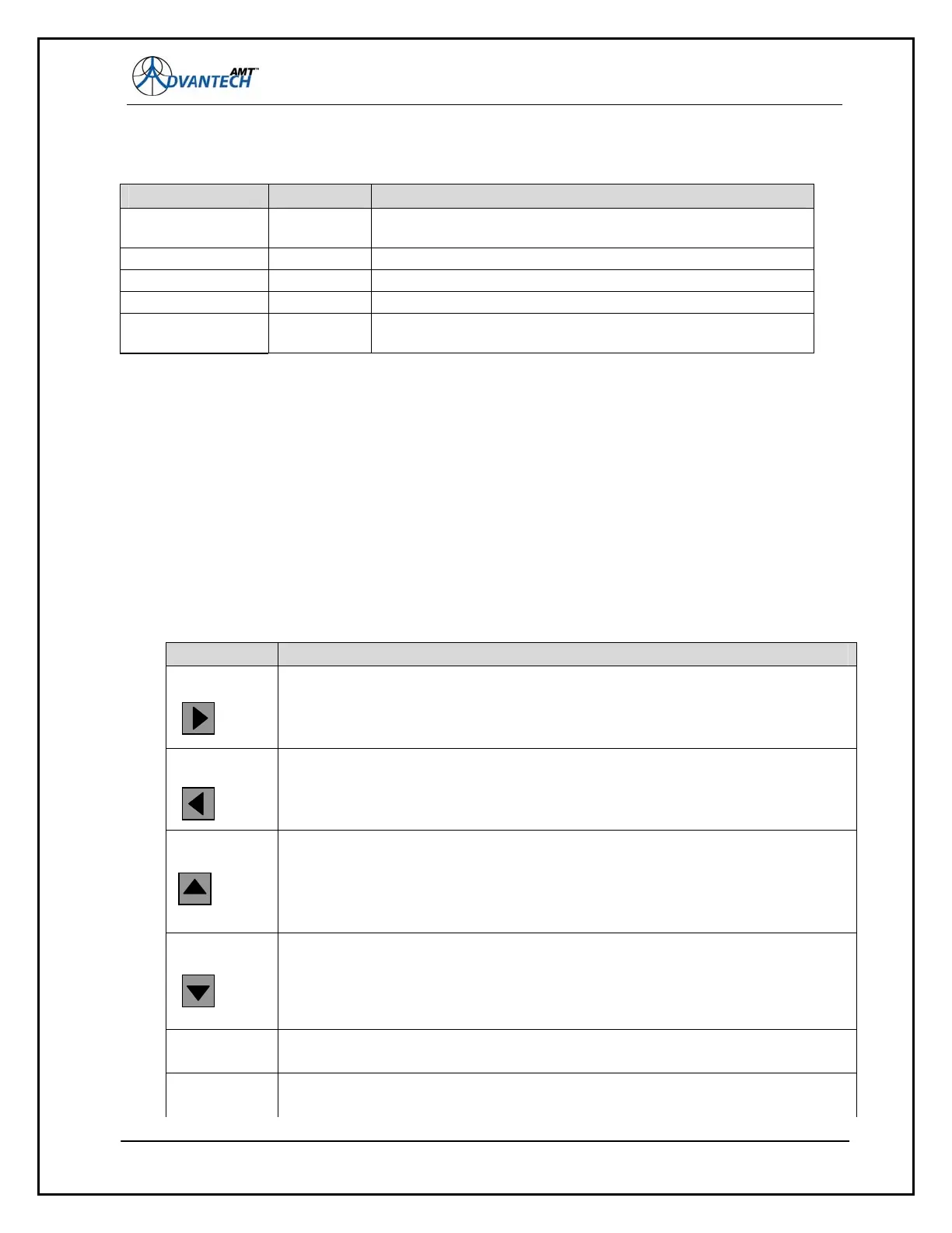
Figure 13: The AMT-73L Front Panel LEDS
4.2.2 Keypad & Display
The advanced front panel adds a Vacuum Florescent Display and a numeric keypad. The screen can
display two lines of 40 characters each with a wide viewing angle. The keypad is comprised of 10
numeric keys [0-9], 4 arrow keys, an ENT (enter) key, and CLR (clear) key. The functions of the
keypad buttons are provided in Figure 14.
The front panel implements a system of seven (7) nested menus, displaying the available options and
parameters. The keypad allows the user to navigate through these menus to monitor and control the
AMT-70 modem by viewing and editing parameters as required.
The display has a blinking solid-block cursor that flashes over the current selected item. The sixteen
push buttons are used to navigate the menu system and to select or edit the required option or
parameter. Functional descriptions of each of the sixteen push buttons can be found in the table
below.
Button Function
RIGHT
Moves the cursor to the right through designated fields.
Can also be used for navigation from the top line to the bottom line of the VFD
display (and vice versa) by toggling to the right through fields.
LEFT
Moves the cursor to the left through designated fields.
Can also be used for navigation from the top line to the bottom line of the VFD
display (and vice versa) by toggling to the left through fields
UP
Moves the cursor up through designated fields.
Primarily used to edit parameters such as L-Band Output frequency etc.
Can also be used to set a ‘+’ on the sign position for signed parameters
Can also be used for navigation from the bottom line to the top line of the VFD
display by toggling up through fields.
DOWN
Moves the cursor down through designated fields.
Primarily used to edit parameters such as L-Band Output frequency etc. Can also
be used to set a ‘-’ on the sign position for signed parameters or can also be
used for navigation from the top line to the bottom line of the VFD display by
toggling down through fields.
ENT
Used to navigate through the menu structure or to accept an edited parameter.
CLR
Used to exit the current menu and return to the previous menu.
62
LED Status Description
Prime Power: Green Indicates that the power supply current is received by the
management card
Transmit On: Green Indicates that the modulator is transmitting.
Receive Lock Green Indicates that demodulator is locked to incoming signal
Receive Fault Red / Off Indicates that the demodulator is exhibiting a fault condition.
TX Fault: Red Indicates that the modulator is not transmitting, due to a fault
(or user intervention).