AMT-70/AMT-73/AMT-75 Installation and Operation
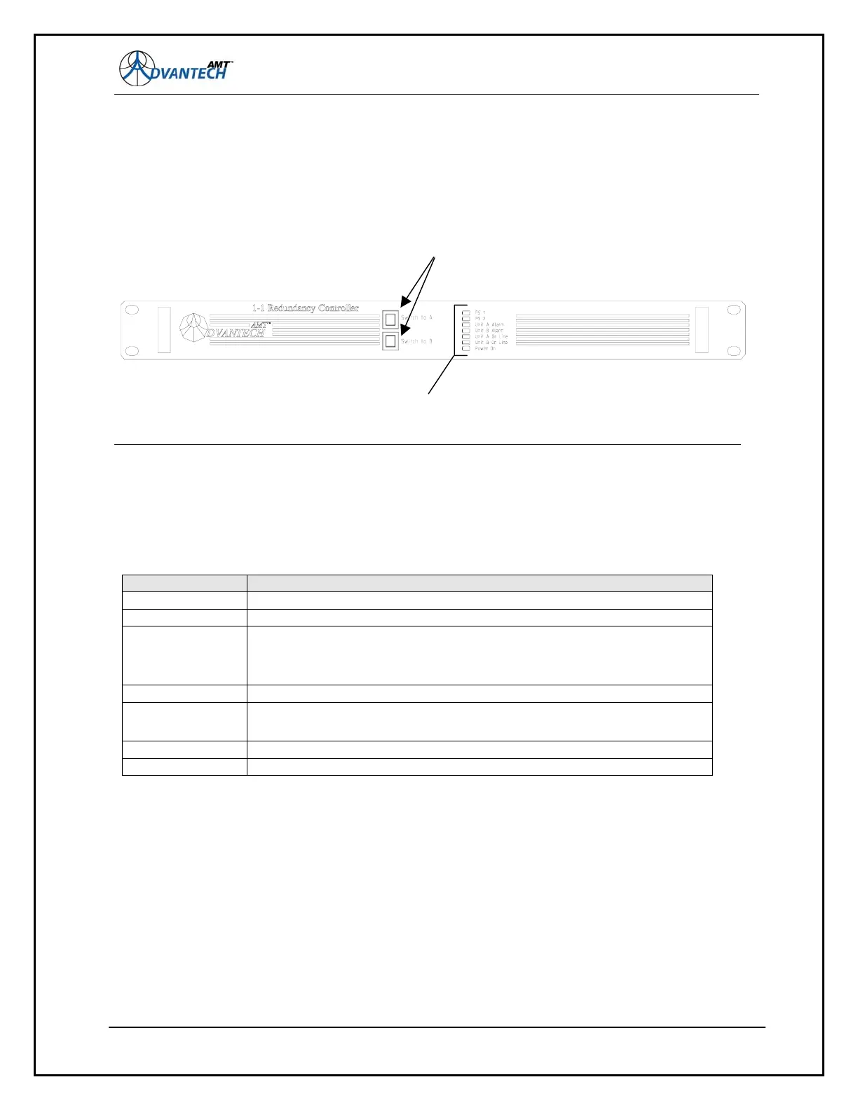
11.1.2.1 Front panel push buttons
The two buttons ‘Switch to A’ and ‘Switch to B’ are used to ‘force’ the redundancy shelf to switch to
either Modem ‘A’ or Modem ‘B’ respectively.
Figure 64: 1-1 Redundancy Controller (R5-530/HSSI only) front panel
11.1.2.2 LED indicators
As illustrated in
Figure 64.
Designation Description
PS 1 Internal Power Supply #1 is ON
PS 2 Internal Power Supply #2 is ON
Unit A Alarm Modem ‘A’ has asserted ‘Summary Fault’ condition
Note - summary fault conditions can be changed. This is described in
Chapter 3.
Unit B Alarm Modem ‘B’ has asserted ‘Summary Fault’ condition
Unit A On Line Modem ‘A’ is active
When illuminated, transmit and receive pass through Modem ‘A’
Unit B On Line Modem ‘B’ is active
Power On +12V sense for Modems and/or Redundancy unit
127
LED indicators
Push buttons