AMT-70/AMT-73/AMT-75 Installation and Operation
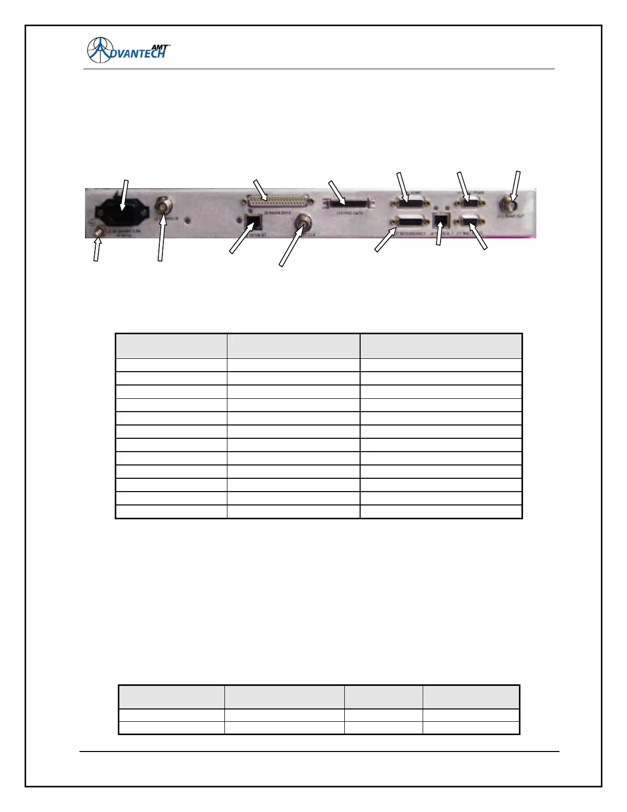
Figure 45: Back Panel Connectors for AMT-73L
Back Panel
Connector Name
Description Connector Type
J1 L Band Output TNC (female)
J2 L Band Input TNC (female)
J3 AC Power In IEC-320
J6 Alarms 15 Pin D
J7 Redundancy 15 Pin D
J8 RIA/TIA 449/422 37 Pin D
J9 Demodulator Ethernet M&C RJ-45
J10 Mod/Demod Ethernet M&C RJ-45
J11 RS-232 M&C DB-9 (female)
J13 RS-485 M&C DB-9 (female)
J14 External Clock BNC (female)
J18 HSSI Subminiature 50-Pin male
8.2 RS-442/449 to RS-530 Adapter Cable
Using an AMT-70 with devices that have an RS-422/RS-449 interface (such as a BER tester)
requires an adapter cable. Although the RS-530 and RS-422/RS-449 interfaces are electrically
identical, they have different connectors.
Use a cable with the pin-outs as listed in the figure below;
Figure 46: TS-422/RS-449 to RS-530 Adapter Cable Pin-Out
RS-422/RS-449
Pin
RS-422/RS-449
Signal
Source RS-530 Pin
P1-17 TT-A DTE P2-24
P1-35 TT-B DTE P2-11
107
AC
Input
Gnd
Lug
L Band
Input
J2
HSSI
Data
Interface
J18
Demod
10/100BaseT
M&C10
J10
RS-422/449
Data
Interface
J8
Ext CLK
J14
Redundancy
J7
Alarms
J6
RS-232
M&C
J11
L Band
Output
J1
Mod/Demod
10/100BaseT
M&C
J9
RS-485
M&C
J13
AC
Input
Gnd
Lug
L Band
Input
J2
HSSI
Data
Interface
J18
Demod
10/100BaseT
M&C10
J10
RS-422/449
Data
Interface
J8
Ext CLK
J14
Redundancy
J7
Alarms
J6
RS-232
M&C
J11
L Band
Output
J1
Mod/Demod
10/100BaseT
M&C
J9
RS-485
M&C
J13