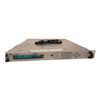
AMT-70/AMT-73/AMT-75 Installation and Operation
Do not place the units beside each other or on top of each other. The exhaust from one unit
can be drawn into the air intake of another.
Make sure the room is properly cooled. Normal cooling may not be sufficient for locations
where the electrical equipment is installed.
Always make sure the unit’s top cover is installed and secured in place.
If it has not already been done, label each cable that will be attached to the unit. This will
prevent confusion and ensures proper connection.
2.3 Power Requirements
The AC power version of the modem can accommodate power requirements found worldwide. The DC
power of the modems either accepts a plus or minus DC voltage from any 32-72 VDC power source.
Please verify that the power system used at the installation site provides a proper earth ground. In
addition, verify that the voltage setting matches the voltage and power provided by the facility where it
will be installed
.
2.3.1 AC Power & Fuse
AC power is applied to the modem via socket JP1 (IEC 320 (M)) on the rear panel.
NOTE:
Only the U.S.-type power cord is shipped with
the AMT-70. Because no international power
cords are shipped with the AMT-70, you must
supply an appropriate approved power cord for
the country of installation.
AMT-70 ist mit einer USA-Schnur nur geliefert.
Da es keine internationalen Schnüre mit dem.
AMT-70 gibt, muß man eine zugelassene
Schnur passend für das besondere Land
liefern.
The fuse assembly is attached to the power receptacle. To remove the fuse, press down on the tab
that extends out just below the power receptacle and between the fuse holder. When replacing the
fuse, make sure to use the exact type and rating marked next to the fuse holder.
AC Fuse: 3.15A 250V (time-delay)
2.3.2 DC Power & Fuse
DC power is applied to the AMT-70 modem via a barrier strip labeled JP1 on the rear panel. This
barrier strip has two screw terminals; one positive (+) and the other negative (-). The two input
terminals are floating (neither lead is connected to chassis ground), and therefore can accommodate a
+48 VDC source. Do not tie the positive lead from the source to chassis ground.
DC Fuse: 6.3A 250V (time-delay)
38
2.4 Modem Rack/Shelf Support
Prior to installing the AMT-70 unit into a rack or shelf, the depth of the supporting structure must be
determined.

 Loading...