AMT-70/AMT-73/AMT-75 Installation and Operation
A.1.1 Setting the transmit levels
The output power level of the modulator is adjustable from 0 to -25 dBm.
10
100 200 300
Length of LMR-600 Cable
BUC
Input
Level
(dBm)
-40
-35
-30
-25
-20
-15
-10
-5
950
2000
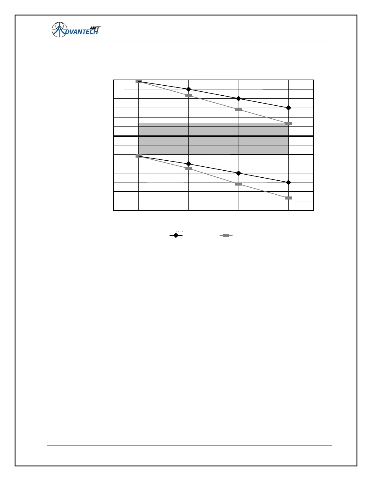
Figure 69: Power Loss in LMR-600 Cable versus Cable Length
The TX gain past the modulator output should be set for the desired EIRP level of the Earth Station.
The ideal situation is to have the gain of the BUC set to give a rated output power of -25 dBm input.
illustrates the power reaching the BUC vs. the cable length between the modulator and the
BUC for two frequencies and with the modulator at maximum and minimum output power. The shaded
area in the previous indicates the useful range of the signal power available from the modulator output,
at the BUC input (for any length of cable up to 300 feet).
Figure 69
Some points to note:
Slightly longer cable lengths are possible with BUCs of higher gain, though the slope delta worsens
with rising frequency.
In this case, LMR-600 cable from Times Microwave Systems is used. LMR-600 cable is low-loss.
If cable with a more typical loss of 12 dB per 100 feet is used, the maximum cable run is
approximately 100 feet. Other cables can be substituted for the LMR-600 Times Microwave
Systems cable, such as the CommScope 3227 cable, which has an attenuation of 6.05 dB @ 1800
MHz, which will increase the distance from the modem to the BUC by up to 200 feet.
133
The BUC power and gain are assumed to be 5W (37 dBm at 1 dB compression) unit with a fixed
gain of 50 dB. This chart indicates that the BUC will be in compression with a 300 ft cable and the
modem output set to +5 dBm and the highest frequency.