AMT-70/AMT-73/AMT-75 Installation and Operation
10.5 TX Carrier Enable
4. As in the above example, set modulator output level using
M&C command “TLEVEL -26”.
6. Using M&C command “TREF ON”, to enable 10 MHz.
1. Double-check modulator IF carrier frequency to insure proper TX frequency.
2. Determine desired TX output level from BUC.
3. Determine modulator output level based upon following formula:
(TX BUC dBm) – (IF to RF BUC gain dB)- (Cable Loss dB) = Modulator carrier
level.
Example: 4 Watts = +36 dBm, BUC gain = 56 dB, cable loss 6 dB.
36 dBm – 56 dB – 6 dB = -26 dBm
5. Double-check BUC output for proper termination.
7. Set the AMT-70 BUC power to ON using the BUCPOWER ON command.
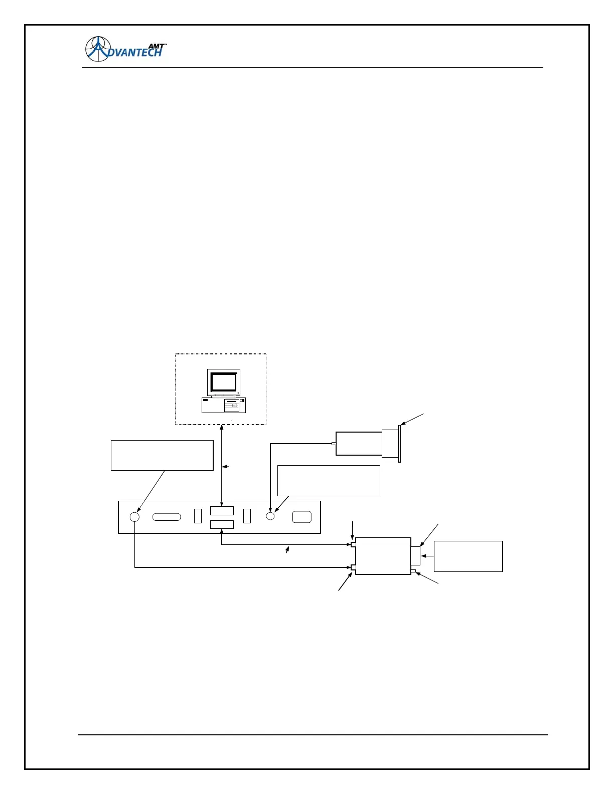
Figure 59: Test Diagram for SSPB and LNB
RX Carrier Acquisition
1. Set the LNB power to ON using the lnbpower ON command.
2. Use M&C command “rspinv to disable the receive Spectrum Invert feature.
3. Use M&C command “rsweep 32”, to enable demodulator sweep at +/- 32 kHz.
4. To check for carrier acquisition, use AMT-70 front panel RX Lock indicator to detect lock.
121
SierraCom BUC
or Advantech
SSPB
J1
J5
M&C RS485
J3
M&C RS-232
J2
LNB
IBM Compatible
M&C Terminal Interface
Caution: +24 or +48 VDC is present
on J1 center conductor. Use BUC
power switch (SW1) or DC block to
prevent damage to test equipment.
Do not use this
LNB connector.
RF Output
RF Input
RS-530
TX/RX DATA
P1
AC Power
SW2
LNB
PWR
SW1
BUC
PWR
SL-2048 Rear Panel
75 Ohm Coax 950 - 1450 MHz
Connectors Type F(female)
50 Ohm Coax 950 - 1450 MHz
Connectors Type N(male)
L Band Connector
Type N (female)
RS-485 Connector
(Provided)
Caution: RF Output
must be properly
terminated to prevent
damage to BUC/SSPB.
Figure D1. Test Diagram 1
Refer to SL-2048 and BUC/SSPB
Manuals for Pin Assignments
Caution: +20 VDC is present on J5
center conductor. Use LNB power
switch (SW2) or DC block to prevent
damage to test equipment.
RS-232 M&C
Interface. Refer
To SL-2048
Manual for
Installation and
Operation.
SierraCom BUC
or Advantech
SSPB
J1
J5
M&C RS485
J3
M&C RS-232
J2
LNB
IBM CompatibleIBM Compatible
M&C Terminal Interface
Caution: +24 or +48 VDC is present
on J1 center conductor. Use BUC
power switch (SW1) or DC block to
prevent damage to test equipment.
Do not use this
LNB connector.
RF Output
RF Input
RS-530
TX/RX DATA
P1
AC Power
SW2
LNB
PWR
SW1
BUC
PWR
SL-2048 Rear Panel
75 Ohm Coax 950 - 1450 MHz
Connectors Type F(female)
50 Ohm Coax 950 - 1450 MHz
Connectors Type N(male)
L Band Connector
Type N (female)
RS-485 Connector
(Provided)
Caution: RF Output
must be properly
terminated to prevent
damage to BUC/SSPB.
Figure D1. Test Diagram 1
Refer to SL-2048 and BUC/SSPB
Manuals for Pin Assignments
Caution: +20 VDC is present on J5
center conductor. Use LNB power
switch (SW2) or DC block to prevent
damage to test equipment.
RS-232 M&C
Interface. Refer
To SL-2048
Manual for
Installation and
Operation.