AMT-70/AMT-73/AMT-75 Installation and Operation
8.7 RJ-45 Ethernet IP Router Connector Pin-Outs (AMT-73L)
AMT-70 Modems may be optionally supplied with an IP router, FRAD (Frame Relay Access Device)
and bridge. With this option, an external router is not required.
For units equipped with IP data routing, an RJ-45 connector (JB) on the rear panel provides access to
the Ethernet data port. The pinout for JB is detailed in section 0 and
Figure 50.
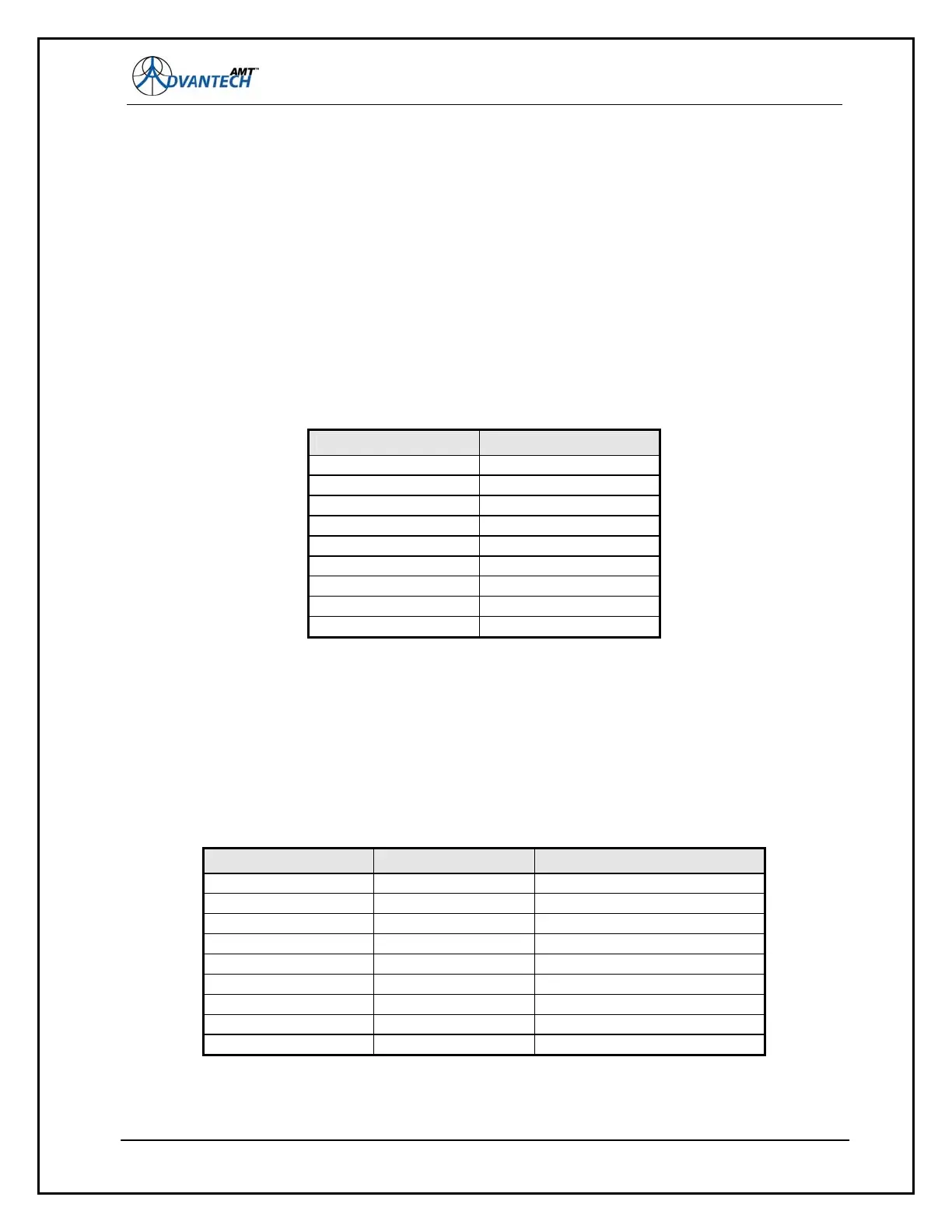
Figure 51: RS-232 Connector Pin-Outs
8.8 RS-232 Connector Pin-Outs
The figure below lists the pin-outs of the 9-pin D connector (labeled P7 on the AMT-70, J11 on the
AMT-73L):
DB-9 Pin Number Description
Pin 1 Not Used
Pin 2 Tx Data
Pin 3 Rx Data
Pin 4 Not Used
Pin 5 Ground
Pin 6 Not Used
Pin 7 Not Used
Pin 8 Not Used
Pin 9 +5 VDC @ 100 mA
Note:
Some PCs do not respond well to the +5 VDC applied to pin 9.
8.9 RS-232 Null Modem Cable Assembly
The figure below lists the pin-outs of a cable assembly that can connect the AMT-70 M&C port to
another RS232 DCE port. The loopback handshaking listed is not required for the AMT-70 modem,
but may be required for the other port.
Figure 52: RS-232 Null Modem Connector Pin-Outs
DB-9 Pin Number
Description AMT-70 Pin Number
Pin 1 RLSD to Pin 4 and 6
Pin 2 TX/RX Data Pin 3
Pin 3 RX/TX Data Pin 2
Pin 4 DTR to Pin 1 and 6
Pin 5 Ground Pin 5
Pin 6 DSR to Pin 1 and 4
Pin 7
111
RTS to Pin 8
Pin 8 CTS to Pin 7
Pin 9 Not Used