AMT-70/AMT-73/AMT-75 Installation and Operation
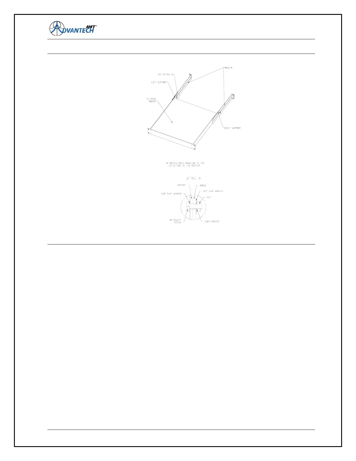
Figure 3: Rack Mount Support kit
Rear support kits are available to secure the AMT-70 unit firmly on to the supporting structure:
1. Kit (19A-230001-001) for racks with a depth of 600 mm
2. Kit (19A-230011-001) for racks with a depth of 800 mm
3. Kit (19A-230021-001) for racks with a depth of 700 mm
Each kit contains two supports, two angles and the associated mounting hardware for the proper
installation on the supporting structure.
Note: The left and right supports are attached to the AMT-70 unit with two #6-32 x 5/16 inch Phillips
countersunk screws. Each angle is attached to a support by one #8-32 x 1/2 inch screw, one # 8 lock
washer, one #8 flat washer 3/8 inch outer diameter, one #8 flat washer 1/2 inch outer diameter, and
one #8-32 hexagonal nut.
2.5 Data Connections (AMT-70 Series)
Data connections for the standard AMT-70 series modems include a RS-530 synchronous data port
and a HSSI synchronous data port, a RS-232 and RS-485 asynchronous M&C port, two Ethernet M&C
ports, and a status M&C port on the back of the chassis. Optionally there may also be (2) ASI BNC
connectors, one for input and one for output. The RS-485 port may be used to manage the BUC and
the LNB/BDC. Chapter 8 provides the connector pin-outs for the various interfaces.
39