AMT-70/AMT-73/AMT-75 Installation and Operation
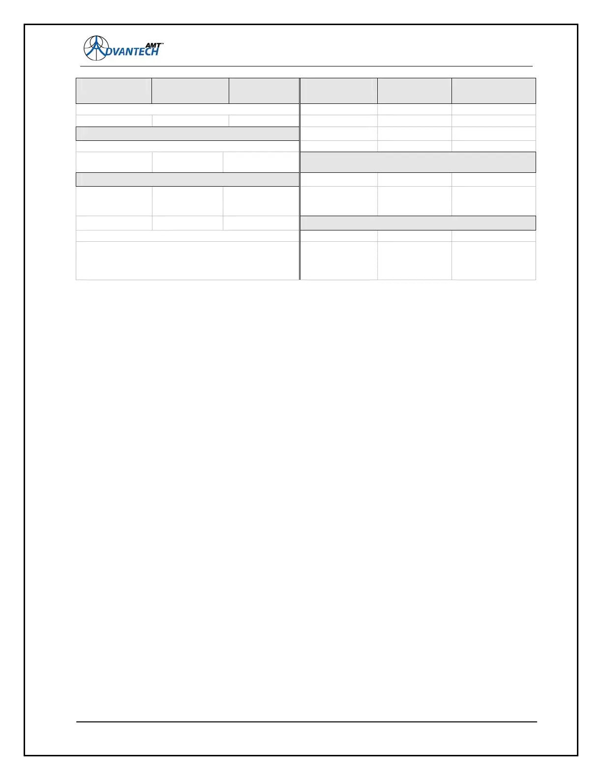
PARAMETER CURRENT
VALUE
DESIRED
VALUE
PARAMETER CURRENT
VALUE
DESIRED
VALUE
DESCRAM ON ON
LNB REF OFF OFF or ON
INTERFACE Menu TX
OFFSET 0 0
TTINV OFF OFF or ON SPTRM FFT OFF ON
CLOCKING LOCAL Any, depending on
operation
INTERFACE Menu RX
INTERFACE Menu LOOPBACK
RTEDGEINV OFF OFF or ON
LINE LOCAL LINE LOCAL LINE LOCAL CLOCKING LOCAL Any, DTE_TT and
LOCAL invoke the
Doppler Buffer
LINE FAR LINE FAR LINE FAR
INTERFACE Menu BUFFER
SYSTEM LOCAL SYSTEM LOCAL SYSTEM LOCAL BUFFER MODE AUTO MANUAL or AUTO
SYSTEM FAR SYSTEM FAR SYSTEM FAR BUFFER DEPTH - - - - 32-65536 bytes,
automatically
selected in AUTO
mode
ENTER the changed values from the TX and RX menus, then page down to RECONFIGURE =
READY, press enter and then enter again to CONFIRM. If other options are selected, the modem
verifies that the parameters selected are within range. If not in range, the display will present a msg.
FEC not supported. If this occurs, use
Figure 10 to determine which parameter is out of range. If the
parameters are within range, the msg. following CONFIRM is Current settings saved.
When all of the parameters are entered and confirmed, now would be the time to connect the modem
to the satellite feed, turn on the TX carrier (SGN = ON), followed by the BUC and LNB voltages and
reference.
Finally, adjust the TX POWER to the desired power level.
4.2 The Front Panel
The AMT-70 can be fitted with one of three front panels: a basic indicator-only version typically used
with the “in the field” units (network downstream) where the units are managed through the network
management facilities; a more advanced front panel which additionally includes a keypad and an LCD
that allows the customer to configure and control the modem directly, and a special active front panel
with a keypad and LCD for the AMT-73L modem.
The interface supports the same command set used to configure the modem via the other M&C
interfaces.
4.2.1 Panel Indicators
60
All AMT-70 front panels include a series of LED indicators. The LEDs indicate critical system status
information as illustrated in the previous are described below. LEDs that illuminate GREEN indicate
that the function is in operation. LEDs that illuminate RED indicate a fault condition.