AMT-70/AMT-73/AMT-75 Installation and Operation
8.10 RS-485 Connector Pin-Outs
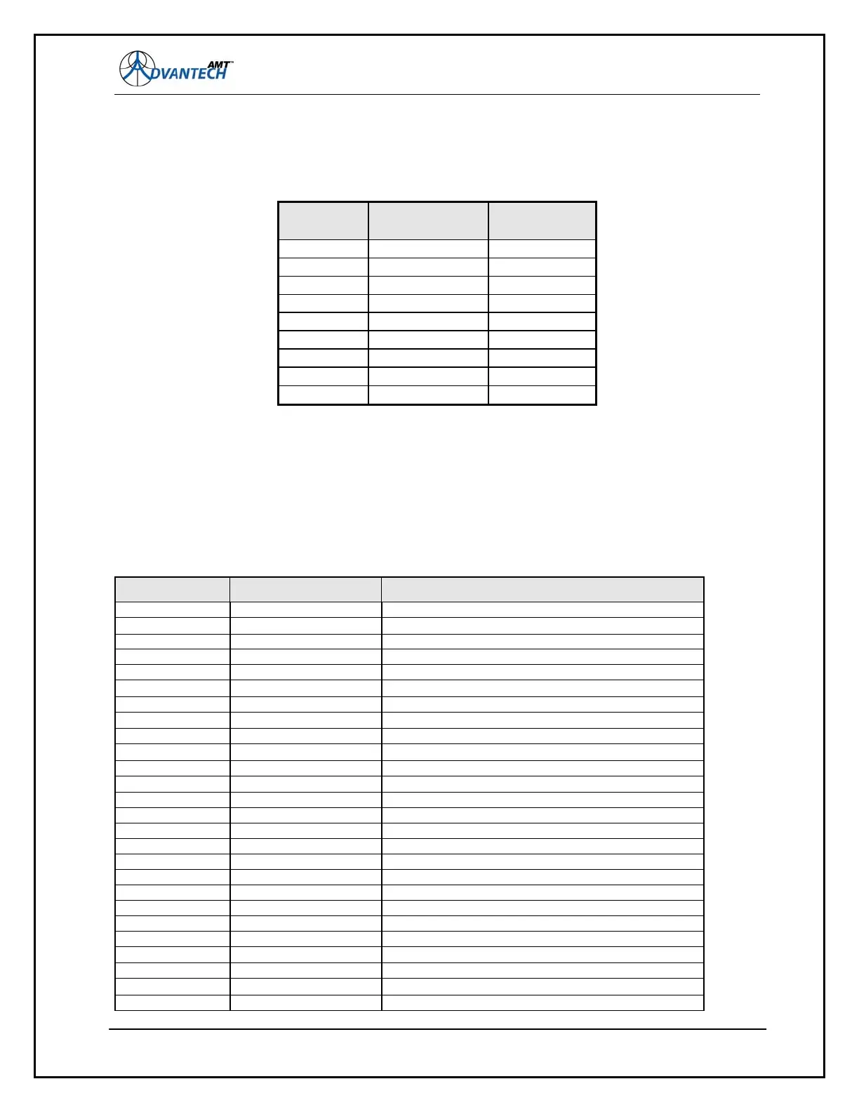
The figure below, lists the pin-outs of the 9-pin D connector (P8 for AMT-70; J13 for AMT-73L):
Figure 53: RS-485 Connectors Pin-Outs
DB-9 Pin
Number
AMT70 AMT73L
Pin 1 Signal Ground RS-485 TX +
Pin 2 Power Detector - Signal Ground
Pin 3 Not Used Signal Ground
Pin 4 RS-485 TX - Signal Ground
Pin 5 RS-485 TX + Signal Ground
Pin 6 Power detector + RS-485 TX -
Pin 7 Not Used Signal Ground
Pin 8***
RS-485 RX + RS-485 RX +
Pin 9*** RS-485 RX - RS-485 RX -
*** For AMT70/73L Pins 8 and 9 are for 2-wire operation. Pins 4, 5, 8, and 9 are for 4-wire
operation.
8.11 EIA/TIA-449 AMT-73L Connector Pin-Outs
The figure below, lists the pin-outs of the 37-pin D connector (labeled J8 on AMT-73L) on the rear
panel.
Figure 54: EIA/TIA-449 Connector Pin-Outs
PIN NUMBER
SIGNAL NAME COMMENT ( Signal Direction )
4 SD A Send Data + to DCE ( Modem )
22 Send Data - to DCE ( Modem ) SD B
6 RD A Receive Data + from Modem
24 RD B Receive Data - from Modem
7 RTS A Request To Send + to Modem
25 RTS B Request To Send - to Modem
9 CTS A Clear To Send + from Modem
27 CTS B Clear To Send - from Modem
11 DSR A DSR + means ( from ) Modem is Ready
29 DSR B DSR - means ( from ) Modem is Ready
12 DTR A Data Term Ready + to Modem
30 DTR B Data Term Ready - to Modem
13 Recvd Line Signal Det From Simple Interface
31 Recvd Line Signal Det From Simple Interface
17 TT A Transmit Timing + from Terminal to Modem
35 TT B Transmit Timing - from Terminal to Modem
5 ST A Send Timing + from Modem to Terminal
23 ST B Send Timing - from Modem to Terminal
8
112
RT A Receive Timing + from Modem to Terminal
26 RT B Receive Timing - from Modem to Terminal
10 LL Local LoopBack from Terminal to Modem
1 GND ( Shield ) Shield is connect to Chassis GND
19 GND ( Shield ) Shield is connect to Chassis GND
37 SC Send Common
20 RC Receive Common
33 SQ Signal Quality