AMT-70/AMT-73/AMT-75 Installation and Operation
3.5 Clock Options and Buffers – Standard Interface Card
The AMT-70 and AMT-73L includes many clocking options that can be selected to satisfy a multitude
of satellite conditions. The standard AMT-70 modulator includes three different options, and the
standard AMT-73L includes five different options. Both the standard AMT-70 demodulator and the
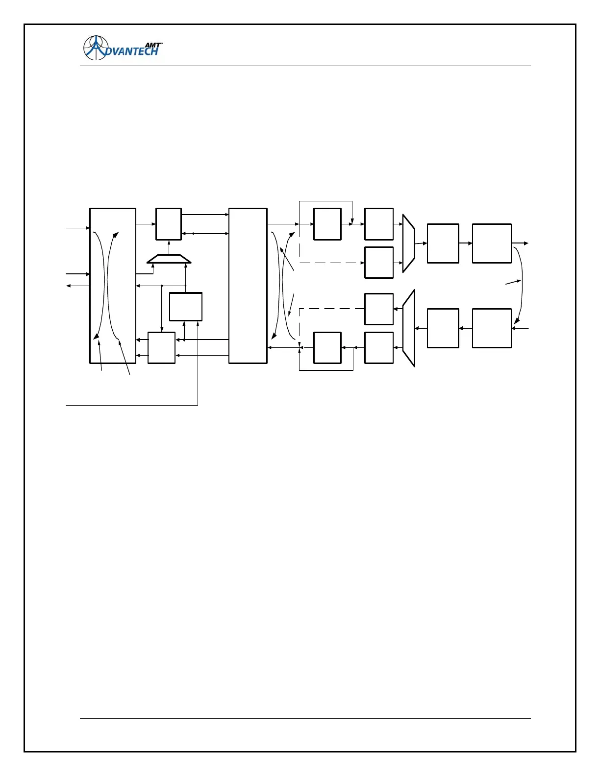
standard AMT-73L have four different options. Figure 7 is a simplified block diagram of the modem
that shows the clocking options.
Figure 7: Functional Block Diagram of AMT-70/73L modem
The terminology used herein is based on the RS-530/422 mnemonics, which includes such
abbreviations as TT for Terminal Timing, ST for Send Timing, RT for Receive Timing, SD for Send
Data, and RD for Receive Data.
The modem is always a DCE (Data Communications Equipment, which normally supplies the clock to
the DTE (Data Terminal Equipment). Crossover cables for interfacing to equipment that supports only
the DCE interface is provided in Chapter 8.
The modulator incorporates a transmit de-jitter buffer that reduces the amount of jitter from the DTE
terminal. It is always in the transmit path, and has a fixed size. This size is varied depending on the
FEC system. A command (TXJTRST) allows the variation of the de-jitter buffer to be measured.
The demodulator incorporates a Doppler Buffer that can be bypassed or activated. The Doppler Buffer
length is operator programmable for length and is automatically centered. The lowest limit is 32 bytes
and the maximum upper limit is 65536 bytes (approx 0.5Mbits). Length is related to data rate; the lower
the data rate, the smaller the buffer.
The Doppler Buffer can also be used as a Plesiochronous Buffer, where the near end modem and far
end modem are operating with dissimilar (but accurate) clocks. Using the buffer in this fashion, clock
slips occur and should be expected. When used as a Plesiochronous Buffer, the size of the buffer
51
DATA I N
Fa r End
Internal
Loopback
RS-530
or
HSSI
Interface
TX
Jitter
Buffer
Encoder &
Sc rambl er
Tur b o
Encoder
TX Reed
Sol omon
Framer/
Def ramer/ IBS
Scrambl er/
Descrambler
Tur b o
Decoder
Vi terbi
Encoder
RX
Doppler
Buf f er
RX Reed
Sol omon
Vi t er bi
Decoder
Modulat or &
IF
Encoder &
Sc rambl er
IF &
Demodulat or
Near End
Interface
Loopback
Demod
Cl oc k
Demod D
RT
RD
SD
TT
Internal
Timi ng
ST
Wri t e
Cl o c k
Wri t e Cl oc k
Serial Dat a
Far End
Interface
Loopback
Near End
Internal
Loopback
IF
Loopback
IF OUTPUT
IF INPUT
DA TA OUT
TT
ST
EXT CL K