Benchmark 1500 - 2000 Boilers
CHAPTER 7 – MAINTENANCE
Page 100 of 182 AERCO International, Inc. • 100 Oritani Dr. • Blauvelt, NY 10913 OMM-0097_0E
10/01/2015 Ph.: 800-526-0288 GF-142
7.11 PLACING THE BOILER BACK IN SERVICE AFTER A PROLONGED
SHUTDOWN
After a prolonged shutdown (one year or more), the following procedures must be followed:
Placing Boiler in Service After Long Shutdown
1. Review installation requirements included in Chapter 2.
2. Inspect all piping and connections to the unit.
3. Inspect exhaust vent and air inlet duct work (if applicable).
4. Perform initial startup per Chapter 4.
5. Perform safety device testing and scheduled maintenance procedures per Chapters 6
and 7 of this manual.
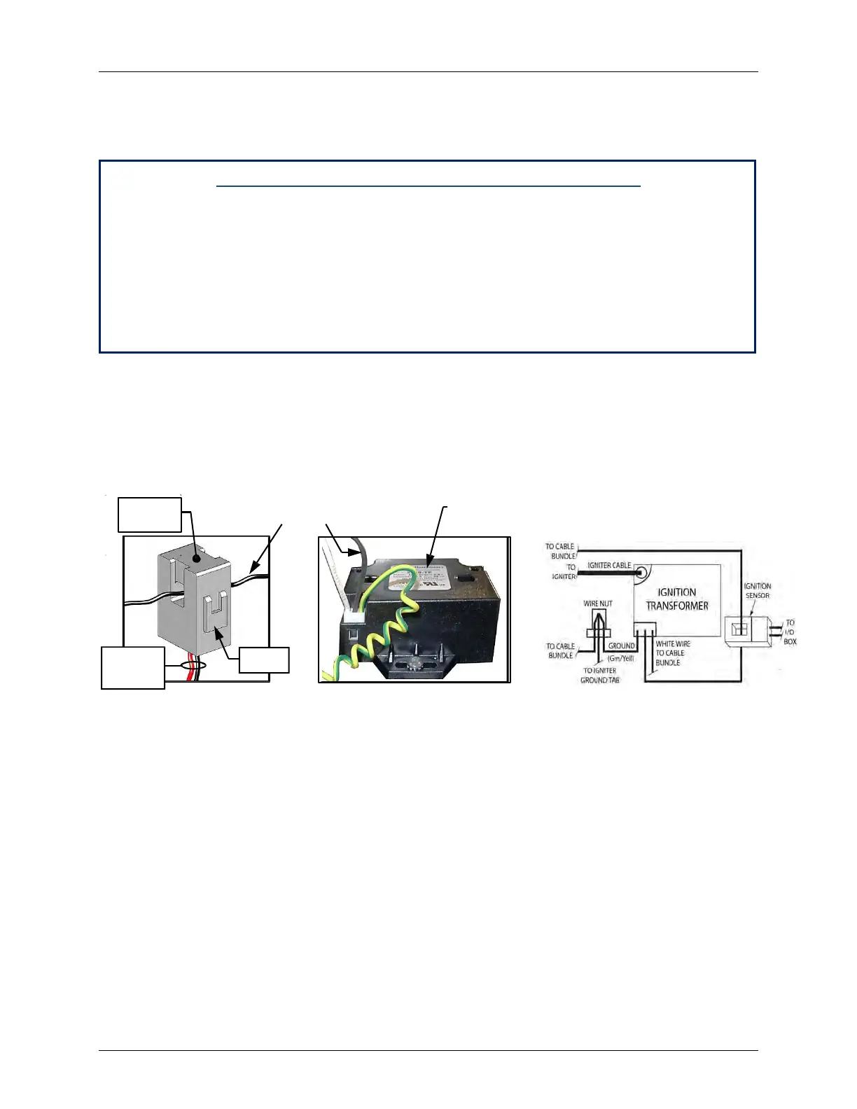
7.12 SPARK MONITOR (AC CURRENT TRANSDUCER)
The spark monitor (P/N 61034) evaluates the strength of the current between the ignition
transformer and igniter-injector. Wire# 140, connected to the ignition transformer (see Figure 7-
11), passes through the monitor’s orifice. If an adequate AC current is not detected in the wire
during ignition, the unit automatically shuts down. The monitor’s wires are connected to the
I/O
board’s Spark Signal
terminals
(see section 2.10.4)
.
Figure 7-11: Spark Detector Sensor (AC Current Transducer) P/N 61034
If the spark monitor needs to be replaced, open the monitor’s orifice by pulling on the tab at
the side, remove Wire# 140, disconnect the monitor’s wires are from the I/O board, remove
the old monitor from its position, install a new monitor in its place, route wire# 140
through the new sensor orifice, and connect the wires to the I/O board’s Spark Signal
terminals, red wire to the positive (+) terminal and black to negative (-).
Transformer