Benchmark 1500 - 2000 Boilers
CHAPTER 2 – INSTALLATION
Page 20 of 182 AERCO International, Inc. • 100 Oritani Dr. • Blauvelt, NY 10913 OMM-0097_0E
10/01/2015 Ph.: 800-526-0288 GF-142
2.6 PRESSURE RELIEF VALVE INSTALLATION
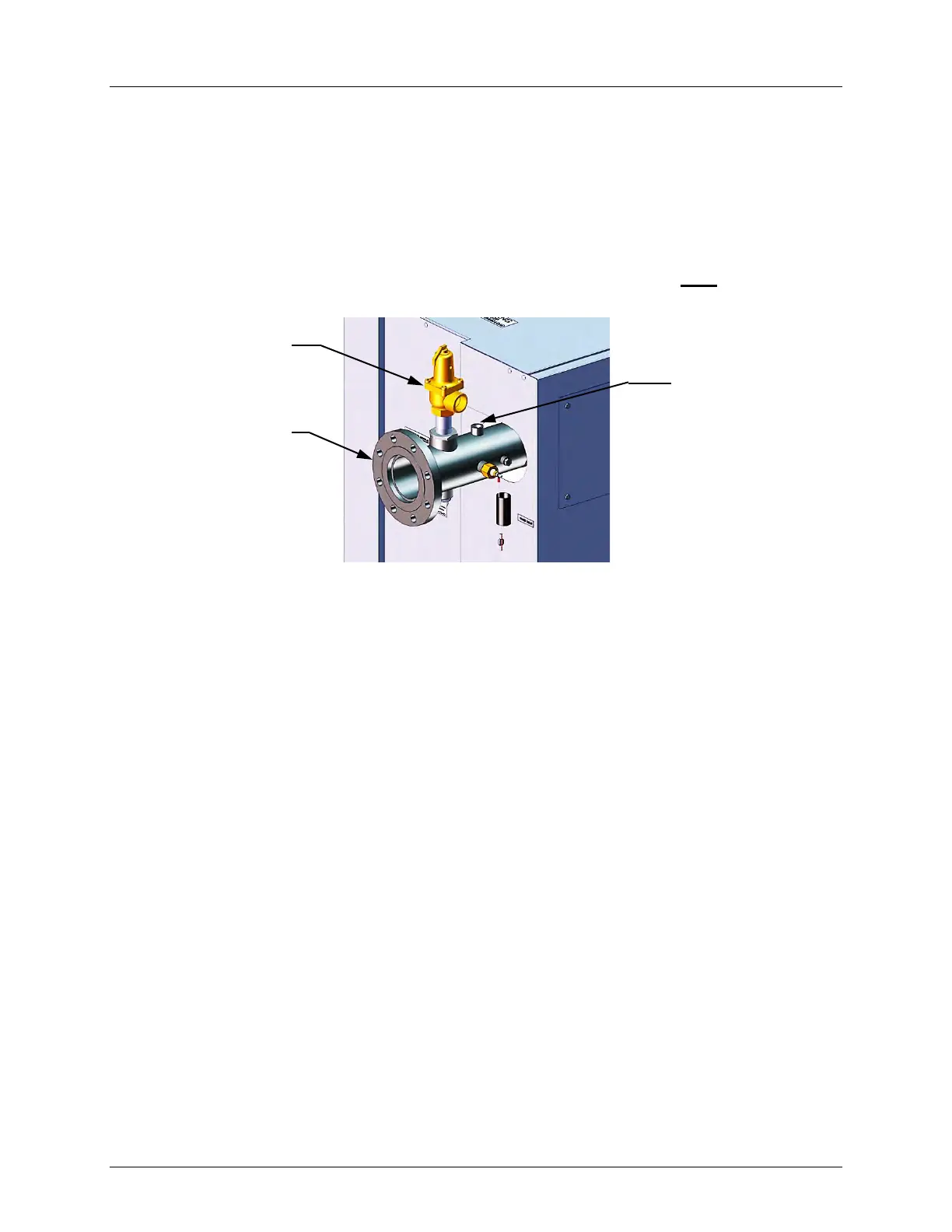
An ASME rated Pressure Relief Valve is supplied with each Benchmark Boiler. The pressure
rating for the relief valve must be specified on the sales order. Available pressure ratings range
from 30 to 160 psi (207 to 1103 kPa). The relief valve is installed on the hot water outlet of the
boiler as shown in Figure 2-4. A suitable pipe joint compound should be used on the threaded
connections. Any excess should be wiped off to avoid getting any joint compound into the valve
body. The relief valve must be piped to within 12 inches (30.5 cm) of the floor to prevent injury
in the event of a discharge. No valves, restrictions, or other blockages are allowed in the
discharge line. In multiple unit installations the discharge lines must NOT be manifolded
together. Each must be individually run to a suitable discharge location.
Figure 2-4: P&T Relief Valve Location
PRESSURE
RELIEF VALVE
4” HOT BOILER
WATER OUTLET
INSTALL
TRIDICATOR GAUGE
HERE
(P/N 123675-TAB)