Benchmark 1500 - 2000 Boilers
CHAPTER 2 – INSTALLATION
OMM-0097_0E AERCO International, Inc. • 100 Oritani Dr. • Blauvelt, NY 10913 Page 25 of 182
GF-142 Ph.: 800-526-0288 10/01/2015
2.9 AC ELECTRICAL POWER WIRING
The AERCO Benchmark Electrical Power Wiring Guide, GF-2060, must be consulted prior to
connecting any AC power wiring to the unit. External AC power connections are made to the
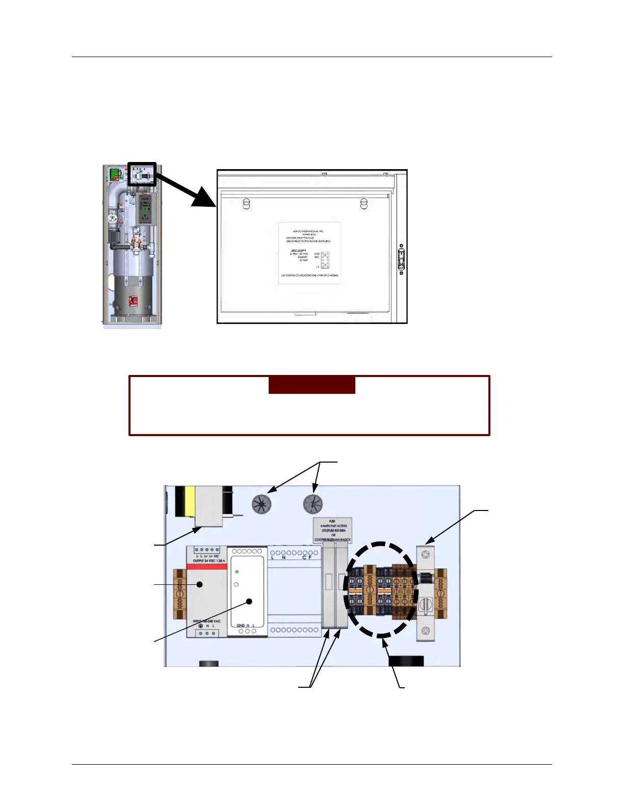
unit inside the Power Box on the front of the unit. Remove the front panel to access the Power
Box, which is mounted in the upper right corner of the unit as shown in Figure 2-8. Loosen the
two upper screws of the Power Box cover and remove cover to access the internal connections
shown in Figure 2-9.
Figure 2-8: Power Box Location with Cover Closed
WARNING!
The power breaker shown in figure 2-9 does NOT remove power
from the terminal blocks.
Figure 2-9: Power Box Internal Components
With the exception of the transformer shown in Figure 2-9, all of the components in the Power
Box are mounted on a DIN rail.
12V POWER
SUPPLY
FUSE BLOCKS (2)
TERMINAL BLOCKS
POWER
BREAKER
TRANSFORMER
24V POWER
SUPPLY
WIRE CONDUITS