Benchmark 1500 - 2000 Boilers
CHAPTER 4 – INITIAL START-UP
Page 54 of 182 AERCO International, Inc. • 100 Oritani Dr. • Blauvelt, NY 10913 OMM-0097_0E
10/01/2015 Ph.: 800-526-0288 GF-142
4.2.1 Required Tools & Instrumentation
The following tools and instrumentation are necessary to perform combustion calibration of the
unit:
• Digital Combustion Analyzer: Oxygen accuracy to ± 0.4%; Carbon Monoxide (CO) and
Nitrogen Oxide (NOx) resolution to 1PPM.
• 0 to 16 inch W.C. (0 to 4000 Pa) manometer or equivalent gauge and plastic tubing.
• 1/4 inch NPT-to-barbed fittings for use with gas supply manometer or gauge.
• Small and large flat blade screwdrivers.
• Tube of silicone adhesive
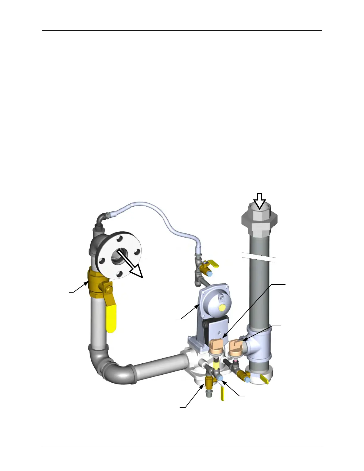
4.2.2 Installing Gas Supply Manometer
The gas supply manometer (or gauge) is used to monitor the gas pressure on the downstream
side of the SSOV during the Combustion Calibration procedures described in section 4.3.
The gas supply manometer is installed at the upstream and/or downstream location shown in
Figure 4-1.
Figure 4-1: 1/4 Inch Gas Plug Location for Combustion Calibration
NATURAL GAS INLET
SSOV
TO
AIR/FUEL
LEAK DETECTION BALL VALVE
1/4” NPT PLUG
(Install manometer here for
Combustion Calibration)
HIGH GAS
PRESSURE
SWITCH
LOW GAS
PRESSURE
SWITCH
MANUAL
SHUT-OFF
VALVE