Benchmark 1500 - 2000 Boilers
CHAPTER 3 – OPERATION
Page 48 of 182 AERCO International, Inc. • 100 Oritani Dr. • Blauvelt, NY 10913 OMM-0097_0E
10/01/2015 Ph.: 800-526-0288 GF-142
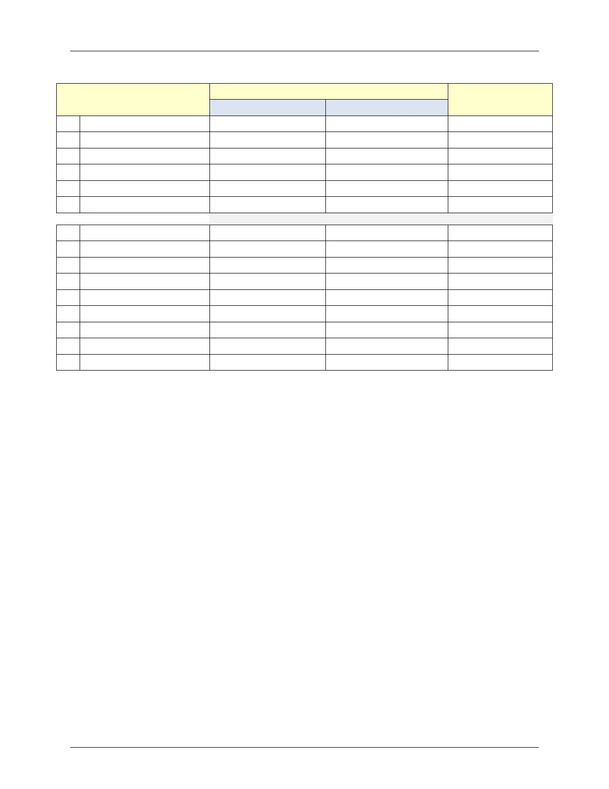
Menu Item Display
Available Choices or Limits
Default
51 BST Deadband Lo 0 25 1
52 Deadband En Time 0 120 Sec 30 Sec
53 BST FR Up Rate 1 120 20
54 BST Bldg Ref Tmp 40°F (4.4°C) 230°F (110°C) 70°F (21.1°C)
55 BST Reset Ratio 0.1 9.9 1.2
56 System Start Tmp 30°F (-1.1°C) 120°F (48.9°C) 60°F (15.6°C)
57
Disabled Enabled Disabled
58 Comm Address 0 127 0
59 BST Min Addr 1 128 1
60 BST Max Addr 1 128 8
61 SSD Address 0 250 247
62 SSD Poll Control 0 1000 0
63 Err Threshold 1 9 5
64 SSD Temp Format Degrees Points Degrees
65 BST Upld Timer 0 9999 sec 0
3.10 START SEQUENCE
When the Control Box ON/OFF switch is set to the ON position, it checks all pre-purge safety
switches to ensure they are closed. These switches include:
• Safety Shut-Off Valve (SSOV) Proof of Closure (POC) switch
• Low Water Level switch
• High Water Temperature switch
• High Gas Pressure switch
• Low Gas Pressure switch
• Blower Proof switch
• Blocked Inlet switch
If all of the above switches are closed, the READY light above the ON/OFF switch will light and
the unit will be in the STANDBY mode.
When there is a demand for heat, the following events will occur:
NOTE
If any of the Pre-Purge safety device switches are open, the
appropriate fault message will be displayed. Also, the appropriate
messages will be displayed throughout the start sequence, if the
required conditions are not observed.