Benchmark 1500 - 2000 Boilers
CHAPTER 2 – INSTALLATION
OMM-0097_0E AERCO International, Inc. • 100 Oritani Dr. • Blauvelt, NY 10913 Page 21 of 182
GF-142 Ph.: 800-526-0288 10/01/2015
2.7 CONDENSATE DRAIN & PIPING
The Benchmark Boiler is designed to condense water vapor from the flue products. Therefore,
the installation must have provisions for suitable condensate drainage or collection.
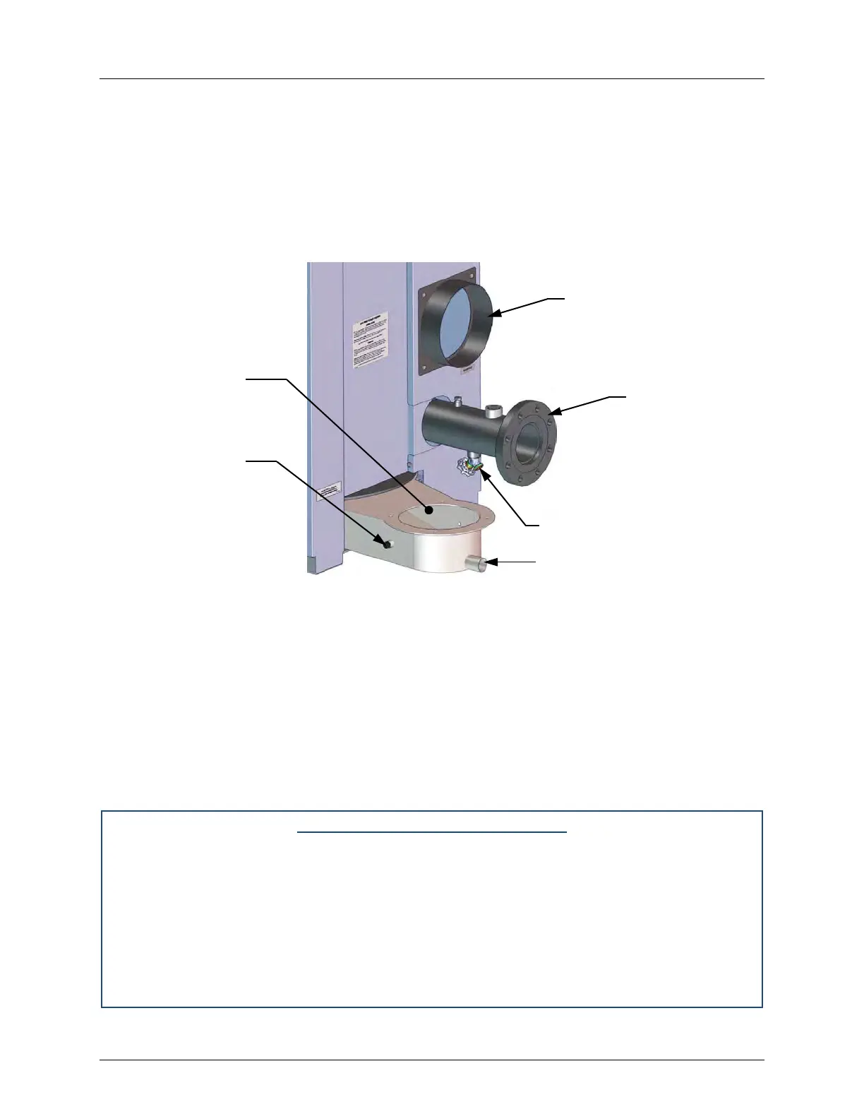
The condensate drain port located on the exhaust manifold (Figure 2-5) must be connected to
the condensate trap (P/N 24441) which is packed separately within the unit’s shipping container.
The condensate trap inlet features two integral O-rings and a thumbscrew to allow direct
connection of the drain port into the trap inlet. See the Condensate trap Installation instructions
and Figure 2-6 on the next page.
Figure 2-5: Condensate Drain Connection Location
A sample condensate trap installation is shown in Figure 2-6. The following general guidelines
must be observed to ensure proper condensate drainage:
• The condensate trap inlet (Figure 2-6) must be level the exhaust manifold drain port.
• The base of the condensate trap must be supported to ensure that it is level (horizontal).
• The trap must be removable for routine maintenance.
While observing the above guidelines, install the condensate trap as follows:
Condensate Trap Installation
1. Connect the condensate trap inlet to the exhaust manifold drain connection by inserting
the drain port directly into the trap adaptor inlet, and then tightening the inlet thumbscrew,
as shown in Figure 2-6. The inlet features two integral O-rings to prevent leakage.
2. At the condensate trap outlet, install a 3/4” NPT nipple.
3. Connect a length of 1” (2.54 cm) diameter polypropylene hose to the trap outlet and
secure with a hose clamp.
4. Route the hose on the trap outlet to a nearby floor drain.
AIR INLET
DRAIN VALVE
CONDENSATE DRAIN PORT