Benchmark 1500 - 2000 Boilers
CHAPTER 9. BOILER SEQUENCING TECHNOLOGY
Page 124 of 182 AERCO International, Inc. • 100 Oritani Dr. • Blauvelt, NY 10913 OMM-0097_0E
10/01/2015 Ph.: 800-526-0288 GF-142
9.3.5 Option 5 - Remote Setpoint with DIRECT WIRED Header Sensor AND 4-
20ma Setpoint Drive
NOTE: Both Header Sensor AND 4-20ma Direct Drive must be wired. See the C-More Controller User
Manual, OMM-0032, GF-112 and ProtoNode User Manual, OMM-0080, GF-129 for more information.
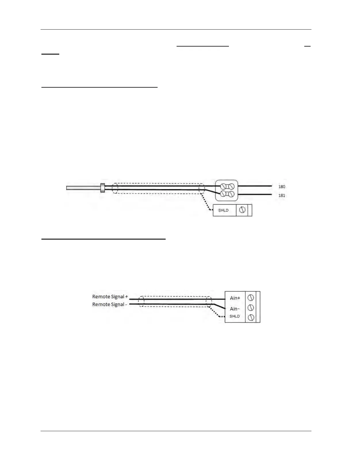
Step 1: Direct Wired Header Sensor Wiring
1. On the MASTER Unit, Connect the Header Temperature Sensor (P/N 61040) to the Feed Forward
(FFWD) terminals on the P-1 Harness Via the terminal block labeled Header Temp sensor in the I/O
Box.
NOTES:
• The header sensor must be installed between 2 and 10 feet (0.61 and 3.1m) downstream of the
LAST boiler in the plant’s supply water header.
• Shielded pair 18 - 22 AWG cable is recommended for header sensor wiring.
• There is no polarity to be observed.
• The ground for the shield is at the “SHLD” terminal in the I/O the Box.
• The sensor end of the shield must be left free and ungrounded.
Step 2: Direct Wired 0-20ma or 4-20ma Wiring
1. Connect the 4-20ma or 0-20ma terminals from the Direct Drive source to the Ain+ and Ain- terminals
on the Master Unit’s I/O Box.
NOTE:
• Shielded pair 18 - 22 AWG cable is recommended for this connection. Polarity must be observed.
• The ground for the shield is at the driver signal source.
Temp Sensor PN 61040 Header Temp Sensor I/O Box