Benchmark 1500 - 2000 Boilers
CHAPTER 4 – INITIAL START-UP
Page 56 of 182 AERCO International, Inc. • 100 Oritani Dr. • Blauvelt, NY 10913 OMM-0097_0E
10/01/2015 Ph.: 800-526-0288 GF-142
4.3 NATURAL GAS COMBUSTION CALIBRATION
The Benchmark boiler is combustion calibrated at the factory prior to shipping. This gas
pressure must be within the following ranges for each model of boiler at full fire:
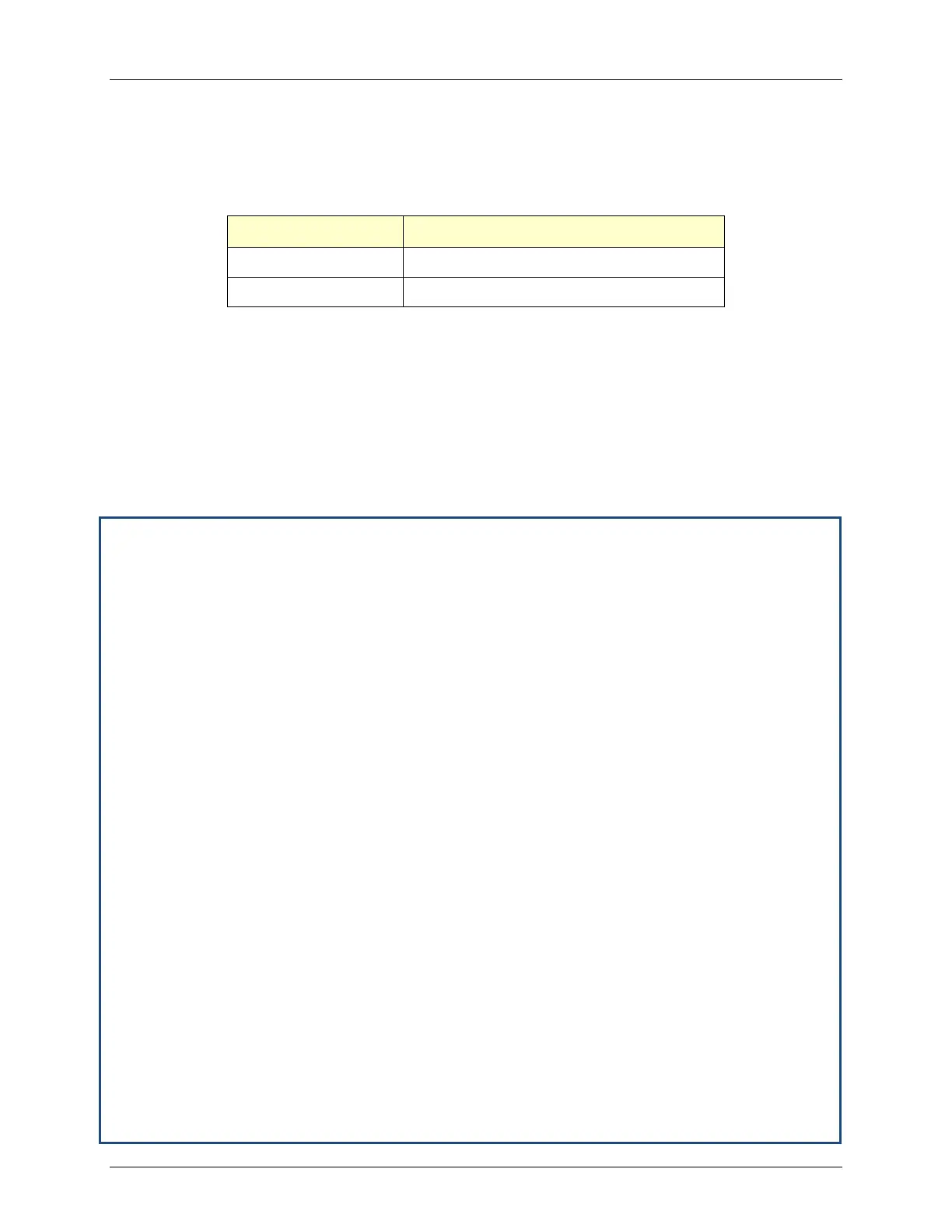
Table 4-1: Nominal Gas Pressure
BMK Boiler Model Nominal Gas Pressure
BMK 1500 3.6” W.C. ± 0.2” W.C. (897 ± 50 Pa)
BMK 2000 3.4” W.C. ± 0.2” W.C. (847 ± 50 Pa)
Recalibration as part of initial start-up is necessary due to changes in the local altitude, gas BTU
content, gas supply piping and supply regulators. Combustion Calibration Test Data sheets are
shipped with each unit. These sheets must be filled out and returned to AERCO for proper
Warranty Validation.
It is important to perform the following procedure as outlined. This will keep readjustments to a
minimum and provide optimum performance.
4.3.1 BMK 1500 Natural Gas Combustion Calibration
Complete the following instructions for natural gas combustion calibration of BMK 1500 units.
BMK 1500 Natural Gas Combustion Calibration
1. Open the water supply and return valves to the unit and ensure that the system pumps
are running.
2. Open the natural gas supply valve to the unit.
3. Set the control panel ON/OFF switch to the OFF position
4. Turn on external ac power to the unit. The display will show loss of power and the time
and date.
5. Set the unit to the MANUAL mode by pressing the AUTO/MAN key. A flashing manual
valve position message will be displayed with the present position in %. Also, the
MANUAL LED will light.
6. Adjust the air/fuel valve position to 0% by pressing the ▼ arrow key.
7. Ensure that the leak detection ball valve downstream of the SSOV is open.
8. Set the ON/OFF switch to the ON position.
9. Change the valve position to 30% using the ▲ arrow key. The unit should begin its start
sequence and fire.
10. Next, verify that the gas pressure downstream of the SSOV is set to 3.6 ± 0.2” W.C. (897
± 50 Pa). If gas pressure adjustment is required, remove the brass hex nut on the SSOV
actuator to access the gas pressure adjustment screw (Figure 4-3). Make gas pressure
adjustments using a flat-tip screwdriver to obtain a gas pressure approximately 3.6” W.C.
± 0.2” W.C. (897 ± 50 Pa).
11. Using the ▲ arrow key, increase the valve open position to 100%. Verify that the gas
pressure on the downstream side of the SSOV settles within the range of 3.6 ± 0.1” W.C.
(897 ± 25 Pa). Readjust the gas pressure if necessary.
12. With the valve position at 100%, insert the combustion analyzer probe into the flue probe
opening and allow enough time for the combustion analyzer reading to stabilize.