Benchmark 1500 - 2000 Boilers
CHAPTER 4 – INITIAL START-UP
Page 62 of 182 AERCO International, Inc. • 100 Oritani Dr. • Blauvelt, NY 10913 OMM-0097_0E
10/01/2015 Ph.: 800-526-0288 GF-142
BMK 2000 Natural Gas Combustion Calibration – Continued
27. Once the oxygen level is within the specified range at 70%, press the ENTER key to
store the selected blower output voltage for the 70% valve position. Record all readings
on the Combustion Calibration Sheets provided.
28. Repeat steps 20 through 27 for valve positions of 50%, 40%, 30% and 18%. The oxygen
(O
2
), nitrogen oxide (NOx) and carbon monoxide (CO) should remain within the same
limits for all valve positions as shown in the following table.
NOTE
If NOx readings exceed the target values shown (<20 ppm),
increase the O
2
level up to 1% higher than the listed calibration
range shown in the table. Record the increased O
2
value on the
Combustion Calibration sheet.
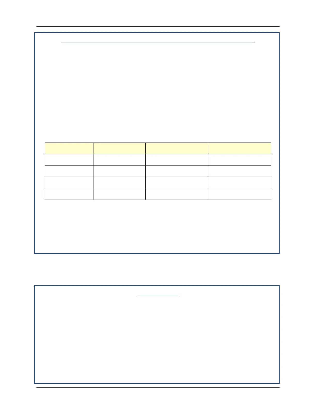
Table 4-7: Combustion Calibration Readings
Valve Position Oxygen (O
2
) % Nitrogen Oxide (NOx) Carbon Monoxide (CO)
50% 6.0% ± 0.5 <20 ppm <100 ppm
40% 6.3% ± 0.5 <20 ppm <100 ppm
30% 6.3% ± 0.5 <20 ppm <100 ppm
18% 6.0% ± 0.5 <20 ppm <100 ppm
29. If the oxygen level at the 18% valve position is too high and the Blower voltage is at the
minimum value, you can adjust the idle screw (TAC valve) which is recessed in the top of
the Air/Fuel Valve (see Figure 4-4). Rotate the screw 1/2 turn clockwise (CW) to add fuel
and reduce the O
2
to the specified level. Recalibration MUST be performed again from
50% down to 18% after making a change to the idle screw (TAC valve).
30. This completes the BMK 2000 Natural Gas combustion calibration procedures.
4.4 REASSEMBLY
Once the combustion calibration adjustments are properly set, the unit can be reassembled for
service operation.
Reassembly
1. Set the ON/OFF switch in the OFF position.
2. Disconnect AC power from the unit.
3. Shut off the gas supply to the unit.
4. Remove the manometer and barbed fittings and reinstall the NPT plug using a suitable
pipe thread compound.
5. Remove the combustion analyzer probe from the 1/4” vent hole in the exhaust manifold.
Replace the 1/4” NPT plug in the manifold.
6. Replace all previously removed sheet metal enclosures on the unit.
7. This concludes reassembly of the unit after combustion calibration.