Benchmark 1500 - 2000 Boilers
CHAPTER 7 – MAINTENANCE
Page 90 of 182 AERCO International, Inc. • 100 Oritani Dr. • Blauvelt, NY 10913 OMM-0097_0E
10/01/2015 Ph.: 800-526-0288 GF-142
IGNITER-INJECTOR MAINTENANCE PROCEDURES – Continued
NOTE
If a replacement igniter-injector (Kit P/N 58023) is being installed,
a compression nut containing a built-in ferrule will be included with
the replacement part. If needed, 3 indexing washers are also
included These washers may be needed to properly position the
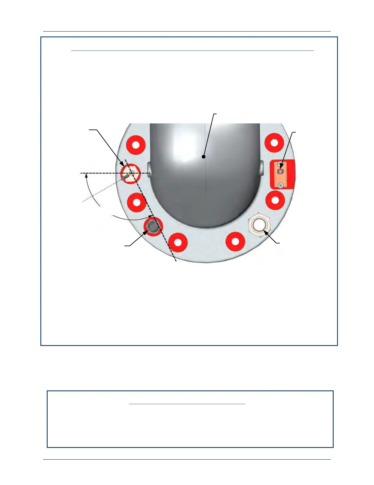
gas injector tube of the igniter-injector within the 120° angle range
shown in Figure 7-3.
Figure 7-3: Igniter-Injector Orientation (Viewed Looking Down from Above)
10. Reinstall the igniter-injector in the burner plate. Torque to 170 - 180 in-lbs (19.2 – 20.3
Nm). DO NOT over tighten.
11. Connect the staged ignition assembly to the gas injector tube of the igniter-injector by
securing the compression nut to the elbow of the staged ignition assembly.
12. Reconnect the igniter-injector cable.
13. Reinstall the shroud on the unit.
7.3 FLAME DETECTOR
The flame detector (kit P/N 24356-1) is located on the burner plate at the top of the unit (see
Figures 7-1 and 7-2). The flame detector may be hot. Allow the unit to cool sufficiently before
removing the flame detector. Inspect or replace the flame detector as follows:
Flame Detector Maintenance
1. Set the control panel ON/OFF switch to the OFF position. Disconnect AC power from the
unit.
2. Remove the top shroud from the unit by grasping the top handle and lifting straight up.
This will disengage the shroud from the four (4) pins in the side panels.
O2 SENSOR
INJECTOR
FLAME
OBSERVATION
PORT
INJECTOR
TUBE