Benchmark 1500 - 2000 Boilers
CHAPTER 7 – MAINTENANCE
Page 88 of 182 AERCO International, Inc. • 100 Oritani Dr. • Blauvelt, NY 10913 OMM-0097_0E
10/01/2015 Ph.: 800-526-0288 GF-142
7.2 IGNITER-INJECTOR
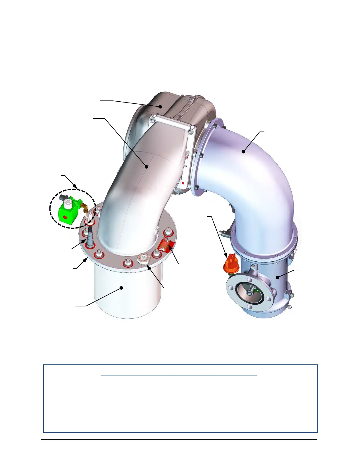
The igniter-injector (Kit P/N 58023) is located on the burner plate at the top of the boiler. In
addition to providing the ignition spark required to light the burner, the igniter-injector also
contains a gas injector tube which connects to the staged ignition assembly. Figure 7-1 shows
the complete burner assembly removed from the boiler and indicates the location of the igniter-
injector flame detector and other related components.
Figure 7-1: Benchmark 1500/2000 Burner Assembly (Removed from Boiler)
The igniter-injector may be hot, therefore, care should be exercised to avoid burns. It is easier to
remove the igniter-injector from the unit after the unit has cooled to room temperature. To
inspect/replace the Igniter:
Igniter-Injector Maintenance Procedures
1. Set the ON/OFF switch on the control panel to the OFF position. Disconnect AC power
from the unit
2. Remove the top shroud from the unit by grasping the top handle and lifting straight up.
This will disengage the shroud from the four (4) pins in the side panels.
3. Disconnect the cable from the igniter-injector (Figure 7-1).
BLOWER
BLOWER
PLENUM
INJECTOR
ASSEMBLY
DETECTOR
BURNER
PLENUM
FLANGE/
BURNER
TOP PLATE
FLAME
OBSERVATION
PORT
BLOCKED
INLET
SWITCH
2
PLENUM