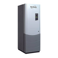
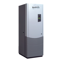
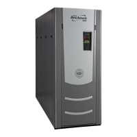
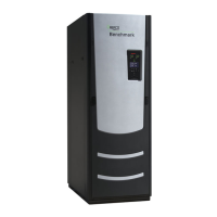
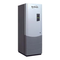
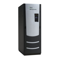
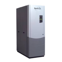
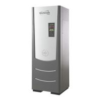
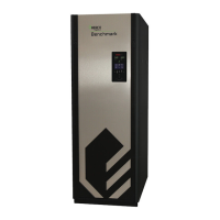
Benchmark 1500 - 2000 Boilers
Installation, Operation & Maintenance Manual (IOMM)
Page 4 of 182 AERCO International, Inc. • 100 Oritani Dr. • Blauvelt, NY 10913 OMM-0097_0E
10/01/2015 Ph.: 800-526-0288 GF-142
3.5 SETUP MENU ....................................................................................................................................... 42
3.6 CONFIGURATION MENU .................................................................................................................... 42
3.7 TUNING MENU ..................................................................................................................................... 45
3.8 COMBUSTION CAL MENU .................................................................................................................. 45
3.9 BST (BOILER SEQUENCING TECHNOLOGY) MENU ....................................................................... 46
3.10 START SEQUENCE ........................................................................................................................... 48
3.11 START/STOP LEVELS ....................................................................................................................... 52
CHAPTER 4. INITIAL START-UP .................................................................................................. 53
4.1 INITIAL START-UP REQUIREMENTS ................................................................................................. 53
4.2 TOOLS AND INSTRUMENTATION FOR COMBUSTION CALIBRATION .......................................... 53
4.2.1 Required Tools & Instrumentation ................................................................................................................. 54
4.2.2 Installing Gas Supply Manometer ................................................................................................................... 54
4.2.3 Accessing the Analyzer Probe Port ................................................................................................................. 55
4.3 NATURAL GAS COMBUSTION CALIBRATION .................................................................................. 56
4.3.1 BMK 1500 Natural Gas Combustion Calibration ............................................................................................. 56
4.3.2 BMK 2000 Natural Gas Combustion Calibration ............................................................................................. 60
4.4 REASSEMBLY ...................................................................................................................................... 62
4.5 OVER-TEMPERATURE LIMIT SWITCHES ......................................................................................... 63
4.5.1 Digital Alarm Switch Checks and Adjustments ............................................................................................... 63
CHAPTER 5. MODE OF OPERATION ........................................................................................... 65
5.1 INTRODUCTION ................................................................................................................................... 65
5.2 INDOOR/OUTDOOR RESET MODE ................................................................................................... 65
5.2.1 Reset Ratio ...................................................................................................................................................... 65
5.2.2 Building Reference Temperature .................................................................................................................... 65
5.2.3 Outdoor Air Temperature Sensor Installation ................................................................................................ 65
5.2.4 Indoor/Outdoor Startup ................................................................................................................................. 66
5.3 CONSTANT SETPOINT MODE ........................................................................................................... 66
5.3.1 Setting the Setpoint ........................................................................................................................................ 67
5.4 REMOTE SETPOINT MODES ............................................................................................................. 67
5.4.1 Remote Setpoint Field Wiring ......................................................................................................................... 68
5.4.2 Remote Setpoint Startup ................................................................................................................................ 68
5.5 DIRECT DRIVE MODES....................................................................................................................... 68
5.5.1 Direct Drive Field Wiring ................................................................................................................................. 69
5.5.2 Direct Drive Startup ........................................................................................................................................ 69
5.6 AERCO CONTROL SYSTEM (ACS) .................................................................................................... 70
5.6.1 ACS External Field Wiring................................................................................................................................ 70
5.6.2 ACS Setup and Startup .................................................................................................................................... 70
5.7 COMBINATION CONTROL SYSTEM (CCS) ....................................................................................... 71
5.7.1 Combination Control System Field Wiring ...................................................................................................... 72
5.7.2 Combination Control System Setup and Startup ............................................................................................ 72
CHAPTER 6. SAFETY DEVICE TESTING ..................................................................................... 73
6.1 TESTING OF SAFETY DEVICES ......................................................................................................... 73
6.2 LOW GAS PRESSURE TEST .............................................................................................................. 74
6.3 HIGH GAS PRESSURE TEST ............................................................................................................. 75
6.4 LOW WATER LEVEL FAULT TEST ..................................................................................................... 76
6.5 WATER TEMPERATURE FAULT TEST .............................................................................................. 76
6.6 INTERLOCK TESTS ............................................................................................................................. 78
6.6.1 Remote Interlock Test..................................................................................................................................... 78
6.6.2 Delayed Interlock Test .................................................................................................................................... 78
 Loading...
