Benchmark 1500 - 2000 Boilers
CHAPTER 3 – OPERATION
Page 50 of 182 AERCO International, Inc. • 100 Oritani Dr. • Blauvelt, NY 10913 OMM-0097_0E
10/01/2015 Ph.: 800-526-0288 GF-142
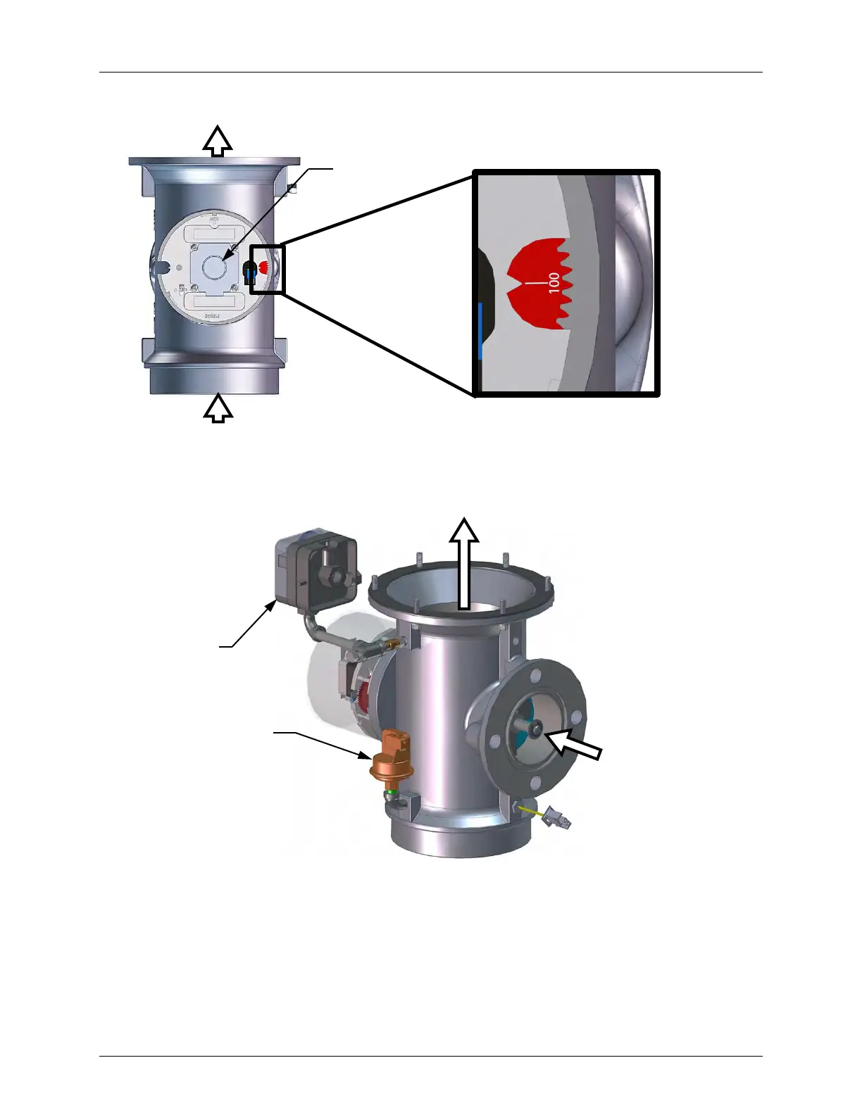
Figure 3-4: Air/Fuel Valve In Purge Position
4. Next, the blower proof switch on the Air/Fuel Valve (Figure 3-5) closes. The display will
show PURGING and indicate the elapsed time of the purge cycle in seconds.
Figure 3-5: Blower Proof Switch
5. Upon completion of the purge cycle, the Control Box initiates an ignition cycle and the
following events occur:
(a) The Air/Fuel Valve rotates to the low-fire (Ignition Position) position and closes the
ignition switch. The Dial on the Air/Fuel Valve (Figure 3-6) will read between 25 and
35 to indicate that the valve is in the low fire position.
PURGE
VALVE POSITION
DIAL AT 100%
AIR/FUEL VALVE
OUTLET TO BLOWER
BLOCKED
INLET
SWITCH
BLOWER
PROOF
SWITCH
AIR/FUEL VALVE
INLET FROM GAS
TRAIN