Benchmark 1500 - 2000 Boilers
CHAPTER 7 – MAINTENANCE
Page 94 of 182 AERCO International, Inc. • 100 Oritani Dr. • Blauvelt, NY 10913 OMM-0097_0E
10/01/2015 Ph.: 800-526-0288 GF-142
Burner Assembly Inspection and Maintenance Procedure – Continued
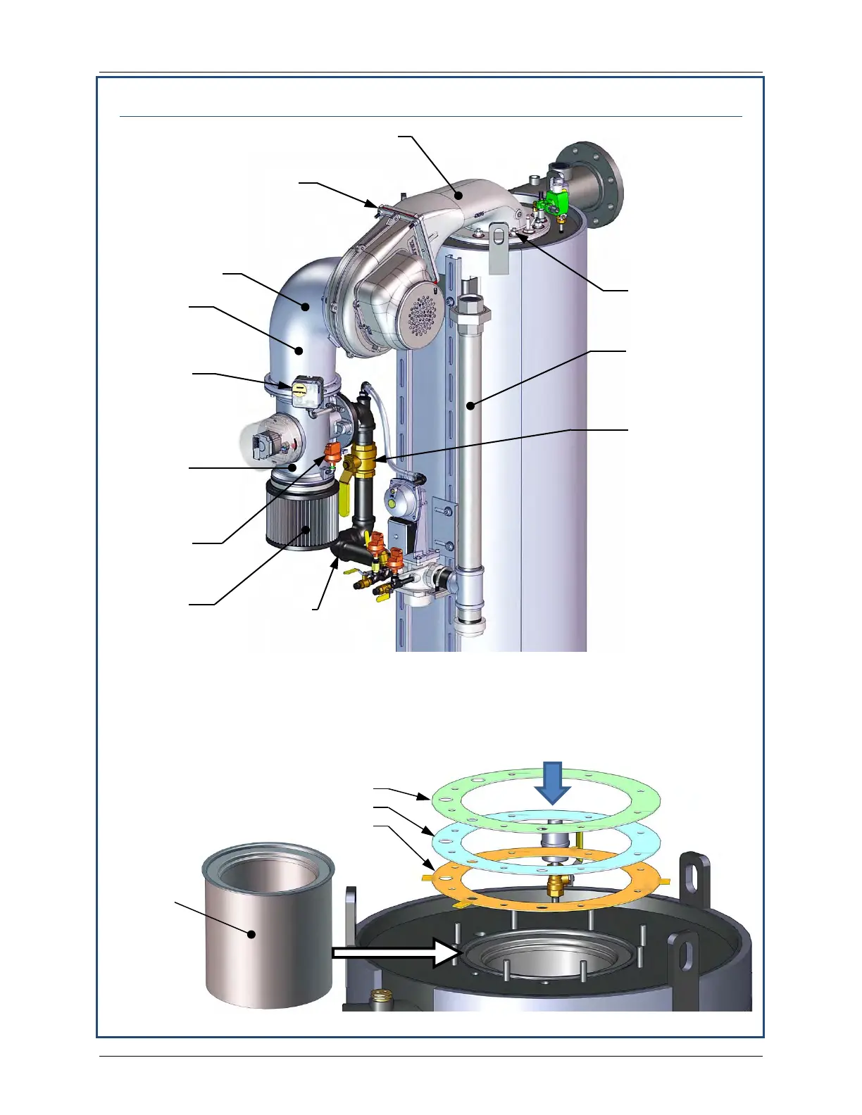
Figure 7-4b: Burner Assembly Mounting Details
Figure 7-5: Bare Burner and Replacement Gaskets Location
HEX NUTS
5/16” x 1-3/4” BOLTS,
5/16” WASHERS &
NYLOCK NUTS
(4 each)
VALVE
PLENUM
AIR
FILTER
VALVE
BLOWER
PLENUM
INLET
SWITCH
PROOF
SWITCH
SHUT-OFF
VALVE
81183 – UPPER RELEASE GASKET
81166 – MIDDLE BURNER GASKET
81186 – LOWER RELEASE GASKET
BURNER
INSTALLED
IN HEAT
EXCHANGER
ASSY.
IMPORTANT!
Use ALL THREE gaskets provided, even if there
is only one existing gasket being replaced.
The LOWER RELEASE
GASKET (P/N 81186) features
four tabs around its periphery.