AfiMilk MPC Installation Manual 44
Chapter
6
Laying Cables and Connecting Wires
Using Connection Boxes to wire the system
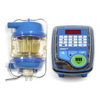
Afimilk MPC connection box is the recommended solution for protecting wired contacts.
The box is a sealed enclosure, incasing terminal blocks for connecting the Afimilk main
cable to external devices it controls. The Afimilk MPC connection box, shown below
incorporates five grommet type cable inlets (Cable inlets are
plugged at delivery). These inlets provide proper seal of
cable inlets into the connection box and may maintain the
non-used inlets sealed. Only plugs of inlets in use need to
be removed prior to threading cables through them.
Grommets are color coded. Each color indicates a cable size
as illustrated in this table.
Inserting Cables into the Connection Box
Proper use of connection box cable inlets ensures keeping the connection box
waterproof.
o Use the appropriate cable inlet in accordance with the width of cable as described
in the tables below.
o Ensure that no inlets are left open
o Tighten the grommet nuts to seal the enclosure after inserting cables as explained
below
Table 2: Grommet color per cables used in Afimilk MPC Installation
Cable Grommet
Apparatus Cable Wire width Color
Afimilk MPC Main Cable Supplied by AfiMilk Black - Larger Inlet
Body Electrodes
Part of Afimilk MPC
Body Blue
Body Valve
Part of Afimilk MPC
Body Red
Pulsator 3 X 0.75mm²/21AWG Blue
Removal Piston 2 X 0.75mm²/21AWG Blue
Vacuum Valve 2 X 0.75mm²/21AWG Blue
Communication RS485 As specified Red
Power Supply 2 X 0.75mm²/21AWG Blue
External Start Button 2 X 0.75mm²/21AWG Blue
Cable
Width
Cable inlet
color
1 - 5mm²
Red
6-7mm²
Blue
9.5mm²+
Black