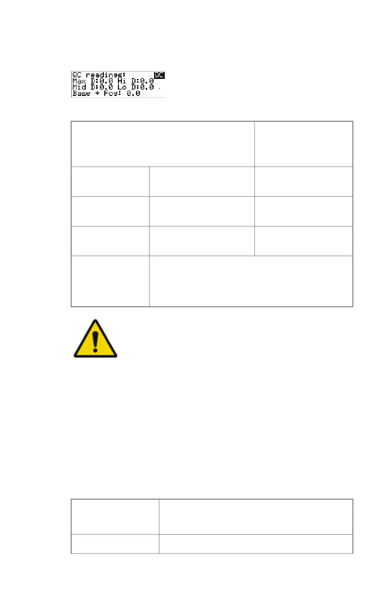
The printer will automatically print the QC test image.
6. After the image is printed, the system will display the optical density
values:
The displayed values represent the following steps on the test film:
Operating Level
Value (Macbeth units)
(according to IEC
1223-2-4 or better)
Low density the density value of the
low density step
0,4 ± 0,05
Mid density the density value of the
mid density step
1,2 ± 0,15
High density the density value of the
high density step
2,0 ± 0,2
Base + Fog, Den-
sity difference
(DD), Maximum
density (Max D)
These values are displayed but not important for
this QC procedure
WARNING:
If the mid density value does not meet or exceeds the
recommended values, the reason must be found and the
problem solved before any further clinical films can be
printed.
7. Record the low, mid and high density levels on Chart 1 (‘Determination of
Operating Levels’).
8. Press the Confirm key to return to the main menu.
9. Repeat step 1 through 8 once a day for five consecutive days, as indicated
on Chart 1.
10. Calculate the average value of the densities from the five images. These
values represent operating levels, or aim values, for each density.
11. Record the respective aim (average) values as the ‘Operating levels’ on
Charts 2A and 2B (‘Daily Density Control Chart’).
The calculated ‘Operating levels’ should be as following:
Operating Level
Value
(according to IEC 1223-2-4 or better)
Low density 0,4 ± 0,05
98 | Drystar 5301, Drystar 5302 | Advanced Operation (key-operator mode)
2831F EN 20210601 1655