1 Installing the GC
Installation and First Startup 15
Step 2 Verify line voltage, voltage settings, and
power cord
1 Locate the power label near the power cord connector on the back of the GC. Compare the
instrument power settings with the laboratory line voltage. See “Power consumption” on
page 16.
2 Verify that the power cord is correct for the voltage and location. “Power cords
available” on page 17.
Electrical shock hazard. To avoid injury, only a qualified person should measure line voltage.
3 Have a qualified person measure the actual power outlet voltage and verify that it meets
the tolerance requirements listed in Table 1 on page 16. See “Grounding” on page 21“ and
“Line voltage” on page 15.
The following sections detail the power specifications and requirements for reference.
Line voltage
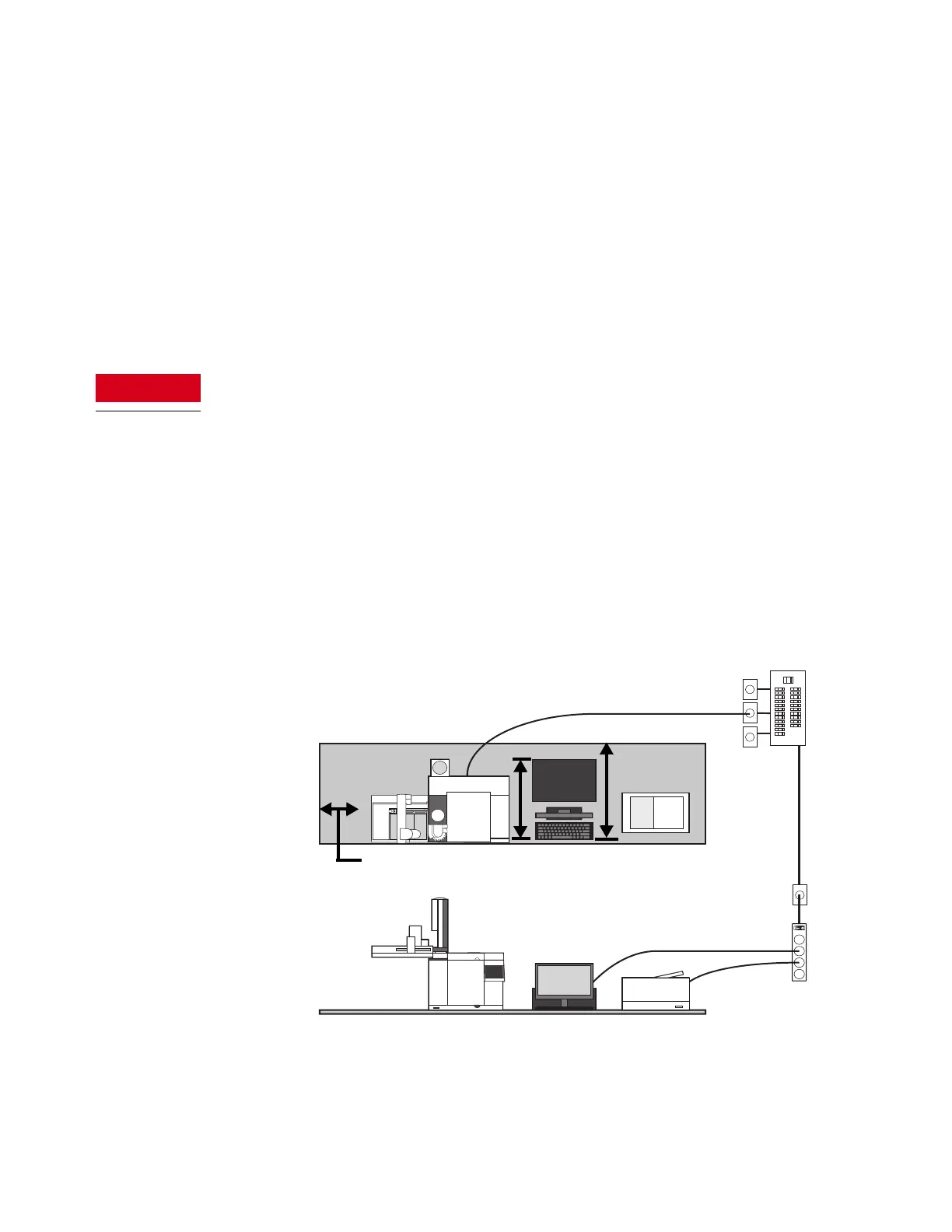
Typical GC System - 8860 GC with computer and printer.
Use isolated circuits with dedicated
grounds for GC and MSD.
Leave 12-in. (31 cm)
open space for
operational access
31-in. (79 cm)
(without heat
deflector
26-in. (66 cm)
(with heat
deflector)

 Loading...


