1 Installing the GC
Installation and First Startup 45
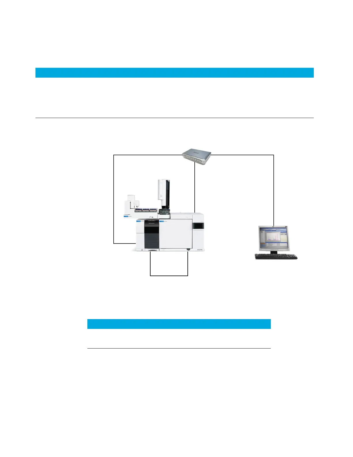
GC / MS / Agilent data system / ALS
Additional cabling configurations
For additional cabling configurations, see Appendix B, “Cabling Diagrams and Remote
Start/Stop”.
Table 9 Cabling for other instruments in a 8860 Series GC system
Instrument 1 Instrument 2 Type of cable Part number
Mass Selective Detector Purge & trap, thermal
desorber, or headspace
sampler
Splitter (“Y”) cable for remote
start/stop, 1 male and 2 female
connectors
G1530-61200
Splitter (“H”) cable for APG remote, 2
male and 2 female connectors
35900-60800
LAN switch or hub
1. LAN cable
8121-0940
GC ComputerMSD
2. APG Remote Cable,
G1530-61200
1. LAN cable
8121-0940
1. LAN cable
8121-0940
Table 10 Cables for a typical GC/MSD or GC/MS system
Number Part number and description
1 G1530-61200, 2-m APG remote cable, 9-pin male/9-pin male
2 8121-0940, Cable, LAN, 25 foot

 Loading...


