B Cabling Diagrams and Remote Start/Stop
72 Installation and First Startup
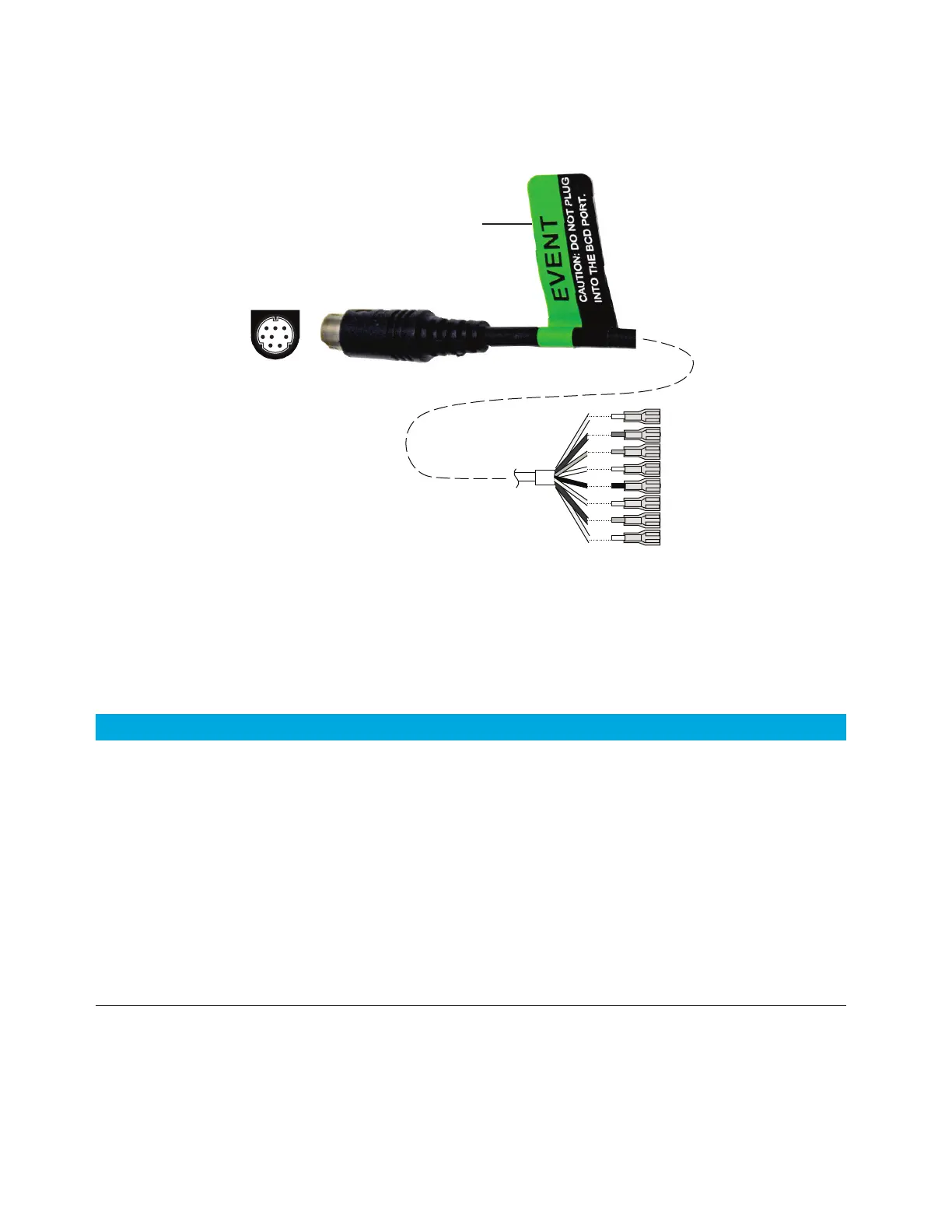
External event cable, G1530-60590
The external event cable has two passive relay contact closures with two 24-volt control
outputs. Devices connected to the passive contact closures must be connected to their own
power sources.
The pin assignments for this cable are listed in Table 15.
When used for external event control, apply label G1580-87200 to identify the cable for EVENT
use.
4
5
6
3
12
78
Wire terminations
Apply label
G1580-87200
Table 15 External events cable
Connector 1 pin Signal name Maximum rating Connector 2, wire color Controlled by valve #
24 volts output
1 24 V output 1 150 mA Yellow 5
2 24 V output 1 150 mA Black 6
3Ground Red
4Ground White
Relay contact closures (normally open)
5 Closure 1 48 V AC/DC, 250 mA Orange 7
6 Closure 1 Green 7
7 Closure 2 48 V AC/DC, 250 mA Brown or violet 8
8 Closure 2 Blue 8

 Loading...


