B Cabling Diagrams and Remote Start/Stop
70 Installation and First Startup
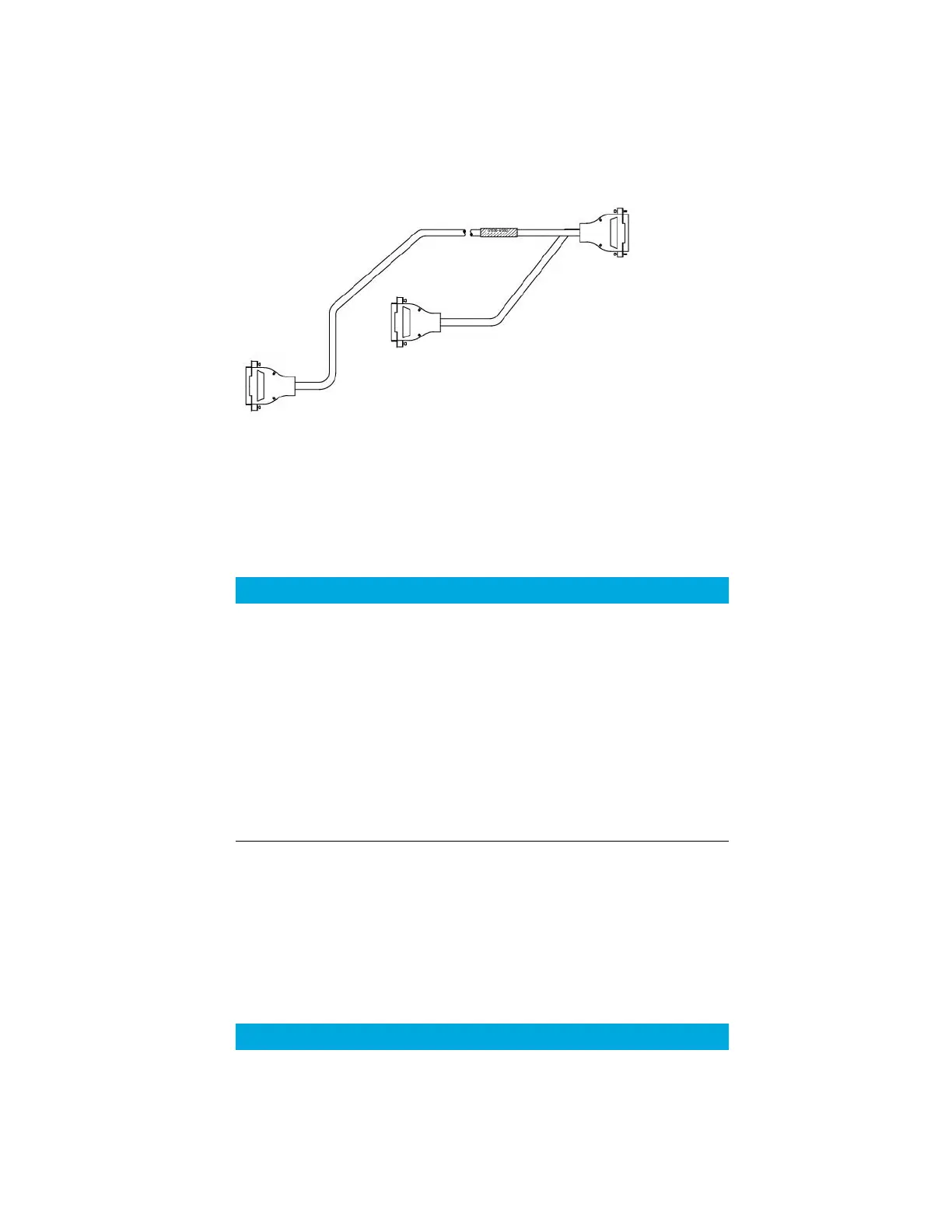
Agilent remote start/stop Y-cable, G1530-61200
Synchronizes the GC with another 2 Agilent instruments.
Figure 23. Remote start/stop cable, GC to Agilent instrument
BCD cable, G1530-60590
The BCD cable connector has eight passive inputs that sense total binary-coded decimal
levels. The pin assignments for this connector are listed in Table 13.
When used for BCD input, apply label G1580-87100 to identify the cable for BCD use.
BCD cable, G1530-61100
The BCD cable connector has eight passive inputs that sense total binary-coded decimal
levels. The pin assignments for this connector are listed in Table 14.
Table 13 BCD input connections
Pin Function Maximum rating
1 Relay 48 V AC/DC, 250 mA
2 Relay 48 V AC/DC, 250 mA
3 LS digit 0
4 LS digit 1
5 LS digit 2
6 LS digit 3
7 MS digit 0
8Ground
Shield Chassis ground
Table 14 BCD cable connections
Connector 1 Pin Connector 2 Pin Ribbon Cable Wire Color
1Brown
2Red

 Loading...


