1 Installing the GC
Installation and First Startup 43
EVENT connector
This connector provides two passive contact closures and two 24-volt outputs for controlling
external devices. The outputs are controlled by valve drivers 5 through 8.
BCD input connector
This connector provides two control relays and a BCD input for a stream selection valve or a
BCD generating device.
BCR/RA connector
This connector is reserved for the optional G3494B RS-232 Barcode Reader. Refer to the GC
Operation Manual.
LAN connector
Standard Local Area Network (LAN) connector, for communication with data systems and
other devices via TCP/IP.
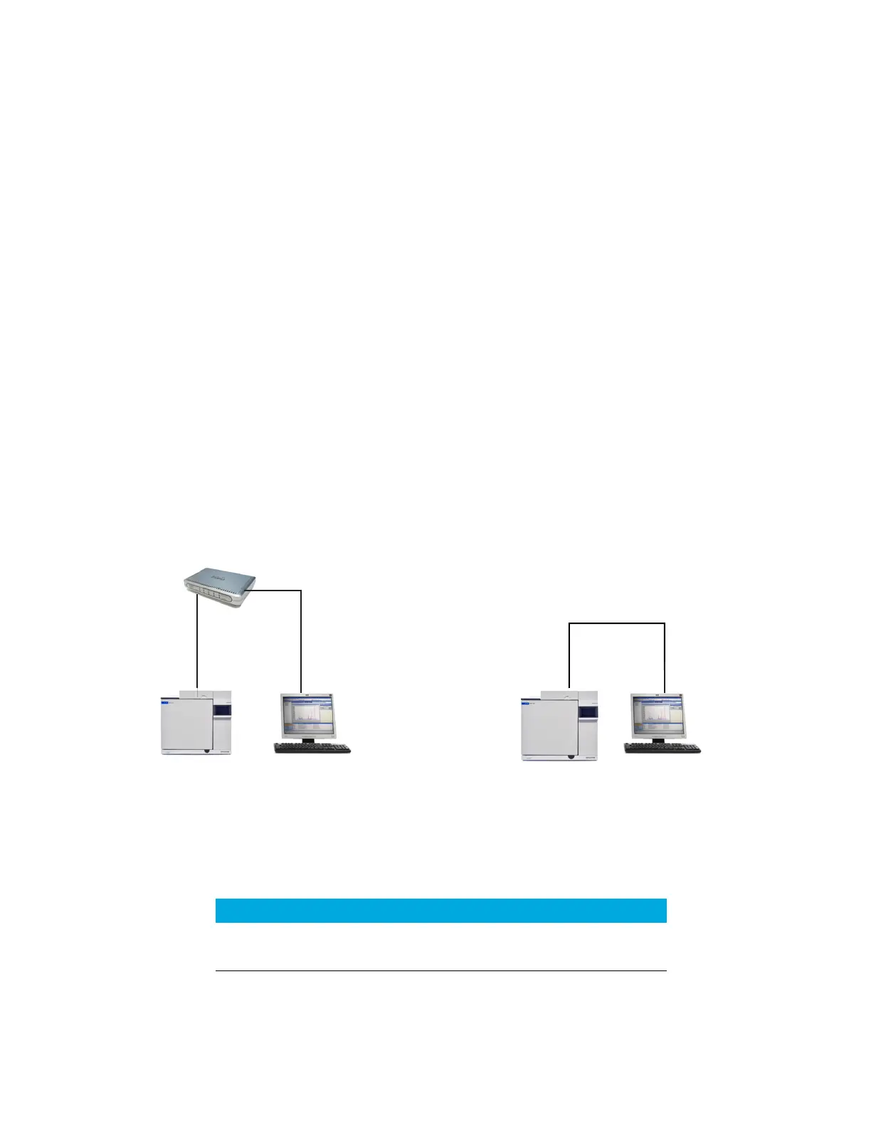
Connecting cables
Use the supplied LAN cable to connect the GC to a LAN switch or hub as shown below in
Figure 12. Other LAN configurations are possible. Refer to your Agilent data system
documentation for details about its supported LAN configurations.
Figure 12. Simple supported LAN configurations: LAN switch or hub (left) and direct connection (right)
LAN switch or hub
LAN cable
8121-0940
Crossover LAN cable 5183-4648
GC GCComputer Computer
LAN cable
8121-0940
OR
Table 7 Typical IP addresses for an isolated LAN
GC Computer
IP address 10.1.1.101 10.1.1.100
Subnet mask 255.255.255.0 255.255.255.0

 Loading...


