1 Installing the GC
42 Installation and First Startup
Step 13 Connect the external cables
In addition to the LAN cable as referenced in “Connect GC to LAN, Local Computer, or
Tablet” on page 22, other cables may be installed for control of the GC’s automatic liquid
sampler (ALS), connecting signal output to integrators, synchronizing the start and end of a
run between various instruments, sensing conditions external to the GC, and controlling
devices external to the GC.
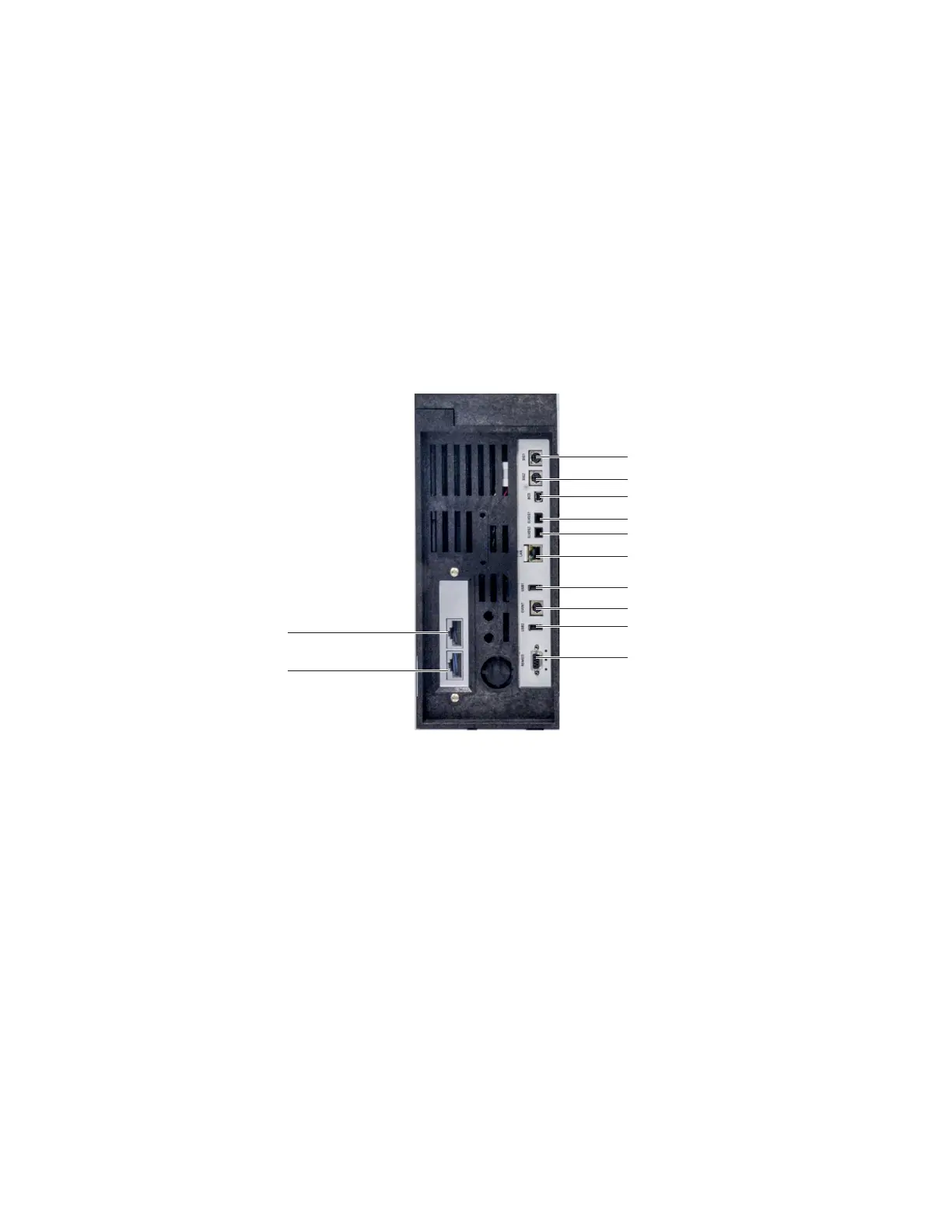
Back panel connectors
The figure below shows the connectors on the back panel of the GC.
See also “Cable Diagrams” on page 67.
Sampler connectors
If using an ALS, connect it to the GC using the following connectors:
ALS 1 Optional. An injector or 150-position sample tray.
ALS 2 Optional. An injector or 150-Position sample tray.
TRAY Optional. The 150-position sample tray (includes optional barcode
reader/heater/mixer control, if purchased).
The SIG (analog output) connectors
Optional. Use SIG1 and SIG2 for analog output signals.
REMOTE connector
Provides a port to remotely start and stop other instruments using the APG protocol. A
maximum of 10 instruments can be synchronized using this connector. See “Using the
Remote Start/Stop Cable” on page 60 for more detail.
ALS1
ALS2
SIG1
SIG2
REMOTE
EVENT
BCD
LAN
ELVDS1
ELVDS2
USB1
USB2

 Loading...


