74 Chapter3
Making EDGE (with GSM) Measurements
Making the Output RF Spectrum Measurement
The GSM standard specifies the tests are run on specified offsets from
the carrier. The instrument identifies this as single offset or multiple
offset modes. The measurement made in these two modes is the same,
except that the multiple offset mode automatically makes the
measurement at all the specified offsets frequencies and lists the
results in a table at the end of the measurement.
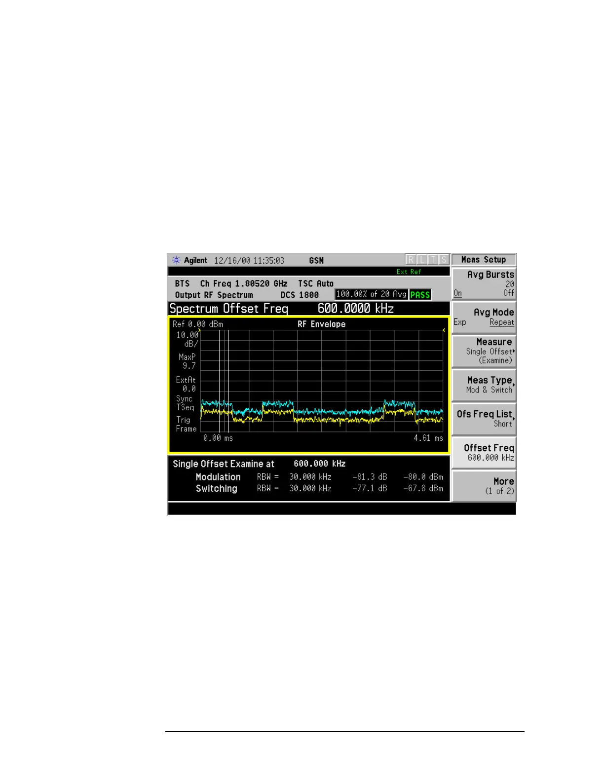
Figure 3-9 shows a single-offset (Examine) trace for an entire GSM
frame with timeslots 0, 2, and 6 turned on and timeslots 1, 3, 4, 5, and 7
turned off. The vertical bars show the portion used to measure power
due to modulation.
Figure 3-9 GSM Frame in Single-Offset (Examine)
The RF envelope trace is displayed. If averaging is turned on, the trace
is then averaged with previous traces. For the modulation
measurement, the user may select the type of trace averaging, either
log-power averaged (Video) or power averaged (RMS). For the switching
transients measurement, the peak of the traces is used. For
modulation, the displayed value is the average of points within the
vertical bars. For transients, the displayed value is the max of all points
for all traces (Max of Peak) over the entire frame.

 Loading...


