1-5
Troubleshooting
A18 CPU Turn–On Test
Checking the A18 CPU Voltages
1. With the external and internal covers removed and the signal generator on its side, turn power
on and check to see if all the power supply LEDs on the A31 Motherboard are on. If any of the
power supply LEDs are not on, refer to “Power Supply Troubleshooting” on page 1-17 to
troubleshoot.
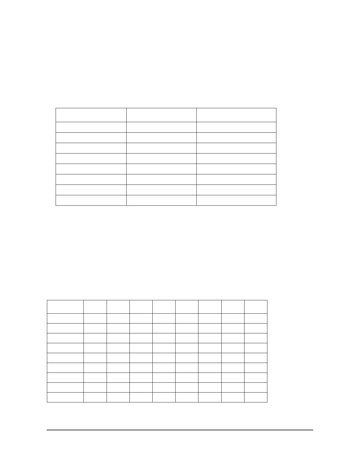
2. If all the power supply LEDs on the motherboard are on, check the A18 CPU and A31
Motherboard connector pins for the voltages listed in the following table.
3. If any main power supply voltage problems are detected, refer to “Power Supply
Troubleshooting” on page 1-17.
4. If all power supply voltages are good, replace A18 CPU.
Verifying the A18 CPU Turn–On Sequence
Verify the A18 CPU turn–on sequence by observing DS1 to DS8 (located along the top) sequence
patterns. DS1 to DS8 should match the sequence shown in Table1-3. Before verifying the turn–on
sequence, make sure all switches in the upper left–hand corner of the A18 CPU are in the CLOSED
(up) position. If the lights fail to step through the sequence, replace A18 CPU.
Connector Supply Voltage Acceptable Range
P223-2, 22 +5 VA +5.2 ± 0.16 Vdc
P223-3 −15 V_In −15 ± 0.45 Vdc
P223-4 +32 V_In +32 ± 0.96 Vdc
P223-21 +15 V_Standby +14.85 ± 0.6 Vdc
P223-23 +15 V_In +15 ± 0.75 Vdc
P223-37 −7 Vdc −7.0 ± 0.14 Vdc
P223-39 +10 Vdc +10.2 ± 0.2 Vdc
P223-40 +8 Vdc +7.95 ± 0.21 Vdc
Table 1-3 A18 CPU LED Sequence Table
Sequence DS1 DS2 DS3 DS4 DS5 DS6 DS7 DS8
1 XXXXXXXX
2 00X00000
3 XXX00000
4 0XXXXXXX
5 00000000
6 XXXXXXX0
7 00XX0X0X
After Preset00000000
X = LED is on; 0 = LED is off