1-110
Troubleshooting
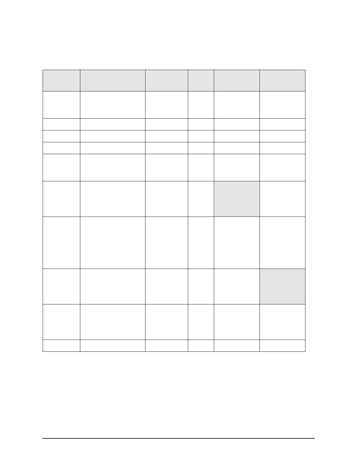
RF Path Description (Frequency Generation, Level Control, and Modulation)
Approximate Device Gains and Losses
Item # Device Gain/Loss
Value
(dB)
Analog
Instruments
Vector
Instruments
1A8 Output
non-1EA
1EA
N/A
N/A
> 17
> 20
✓✓
2 A12 Opt 1E6 Pulse Mod. Loss < 3
✓✓
3 A23 Lowband Coupler Loss < 3
✓✓
4 A28 YO Output N/A > 11
✓✓
5 A29 20 GHz Doubler
J1 to J2
J1 to J3 and J4
Gain
Loss
> 1
< 18
✓✓
6 A35 3–20 GHz I/Q Mod.
Bypass mode, J5 to J1
3.2 to 12.8 GHz
12.8 to 20 GHz
Gain
Loss
> 0
< 2
✓
7 A30 Modulator Filter
J1 to J2 (non-1EA)
J1 to J2 (1EA)
J1 to J4 (non-1EA)
J1 to J4 (1EA)
J3 to J4
Gain
Gain
Gain
Gain
Loss
> 0
> 8
> 1
> 9
< 3
✓✓
8
A27 40 GHz Doubler
J1 to J2 (> 20 GHz)
J3 to J2 (< 3.2 GHz)
J3 to J2 (3.2 to 20 GHz)
Loss
< 8
< 1
< 2.5
✓
9
A24 Highband Coupler
< 3.2 GHz
2–20 GHz
> 20 GHz
Loss
< 2.5
< 0.5
< 2.5
✓✓
10 AT1 (0 dB step) Loss < 2.5
✓✓