2-96
Assembly Replacement
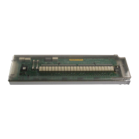
A35 3-20 GHz I/Q Modulator (E8267C Models Only)
A35 3-20 GHz I/Q Modulator (E8267C Models Only)
Tools Required
• needle-nose pliers
Removal Procedure
Refer to Figure 2-46 for this procedure.
1. Disconnect the power cord.
2. Remove the covers from the signal generator. Refer to "Outer Instrument Cover" on page 2-5
and "Inner Instrument Cover" on page 2-7.
3. Position the signal generator with the front panel facing you.
4. Using the T-10 driver, remove the four screws from the Baseband Generator cover.
5. Using the needle-nose pliers, disconnect the following flexible cables:
• W63 from A35J5
• W62from A35J6
• W49 from A35J7
• W50 from A35J8
• W61 from A35J9
• W60 from A3510
• W59 from A35J11
• W58 from A35J12
• W57 from A35J13
• W56 from A35J14
6. Lift the retention levers and disconnect the A35 3-20 GHz I/Q Modulator from the
A31 Motherboard.
7. Lift the A35 3-20 GHz I/Q Modulator out of the slot.
Replacement Procedure
• Reverse the order of the removal procedure.
• Perform the post-repair adjustments and performance tests that pertain to this removal
procedure.



 To Next Page

