Making Measurements 2
Testing Diodes
U1231A/U1232A/U1233A User’s Guide 45
Testing Diodes
Set up your multimeter to test diodes as shown in
Figure 2- 14. Probe the test points and read the display.
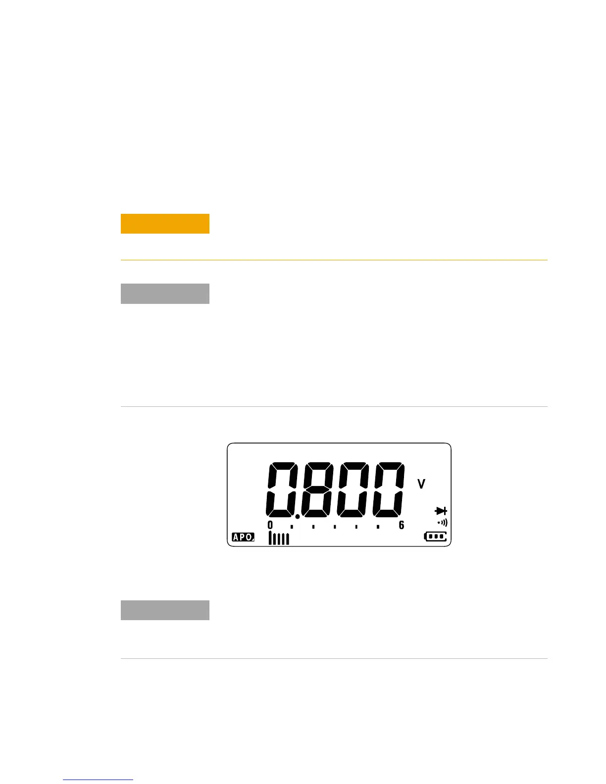
Figure 2-12 Diode display
To avoid possible damage to your multimeter or to the equipment under
test, disconnect the circuit power and discharge all high-voltage
capacitors before testing diodes.
• Use the diode test to check diodes, transistors, silicon controlled
rectifiers (SCRs), and other semiconductor devices. A good diode
allows current to flow in one direction only.
• This test sends a current through a semiconductor junction, and then
measures the junction’s voltage drop.
• Connect the red test lead to the positive terminal (anode) of the diode
and the black test lead to the negative terminal (cathode). The cathode
of a diode is indicated with a band.
Your multimeter can display the forward bias of a diode up to
approximately 2.1 V. The forward bias of a typical diode is within the range
of 0.3 V to 0.8 V; however, the reading can vary depending on the
resistance of other pathways between the probe tips.
 Loading...


