Performance Tests and Calibration 6
Agilent U1251B/U1252B User’s and Service Guide 143
For serial numbers below MY51530001, the 10 kHz input frequency is
applied to those marked with an asterix (*)
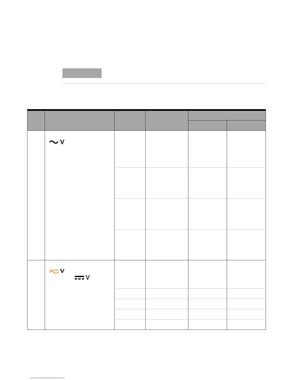
Tab l e 6-4 Adjustment table
Step Test Function Cal Range Input
Cal Item
U1251B U1252B
1 Turn the rotary switch to the
position
5 V 0.3 V,1 kHz 0.3000 V 0.3000 V
3 V, 1 kHz 3.0000 V 3.0000 V
3 V, 20 kHz * 3.0000 V 3.0000 V
50 V 3 V, 1 kHz 03.000 V 03.000 V
30 V, 1 kHz 30.000 V 30.000 V
30 V, 20 kHz * 3.0000 V 30.000 V
500 V 30 V,1 kHz 030.00 V 030.00 V
300 V,1 kHz 300.00 V 300.00 V
300 V, 20 kHz * 3.0000 V 300.00 V
1000 V 30 V, 1 kHz 0030.0 V 0030.0 V
300 V, 1 kHz 0300.0 V 0300.0 V
300 V, 20 kHz * 3.0000 V 0300.0 V
2 Turn the rotary switch to
position (for model
U1252B), to
position
(for model U1251B)
Short Dual Banana Plug
with copper wire
short between 2
terminals
SHort SHort
5 V 3 V 3.0000 V 3.0000 V
50 V 30 V 30.000 V 30.000 V
500 V 300 V 300.00 V 300.00 V
1000 V 1000 V 1000.0 V 1000.0 V

 Loading...


