Publication 1734-UM002C-EN-P - July 2003
Default Data Maps D-7
Channel Status
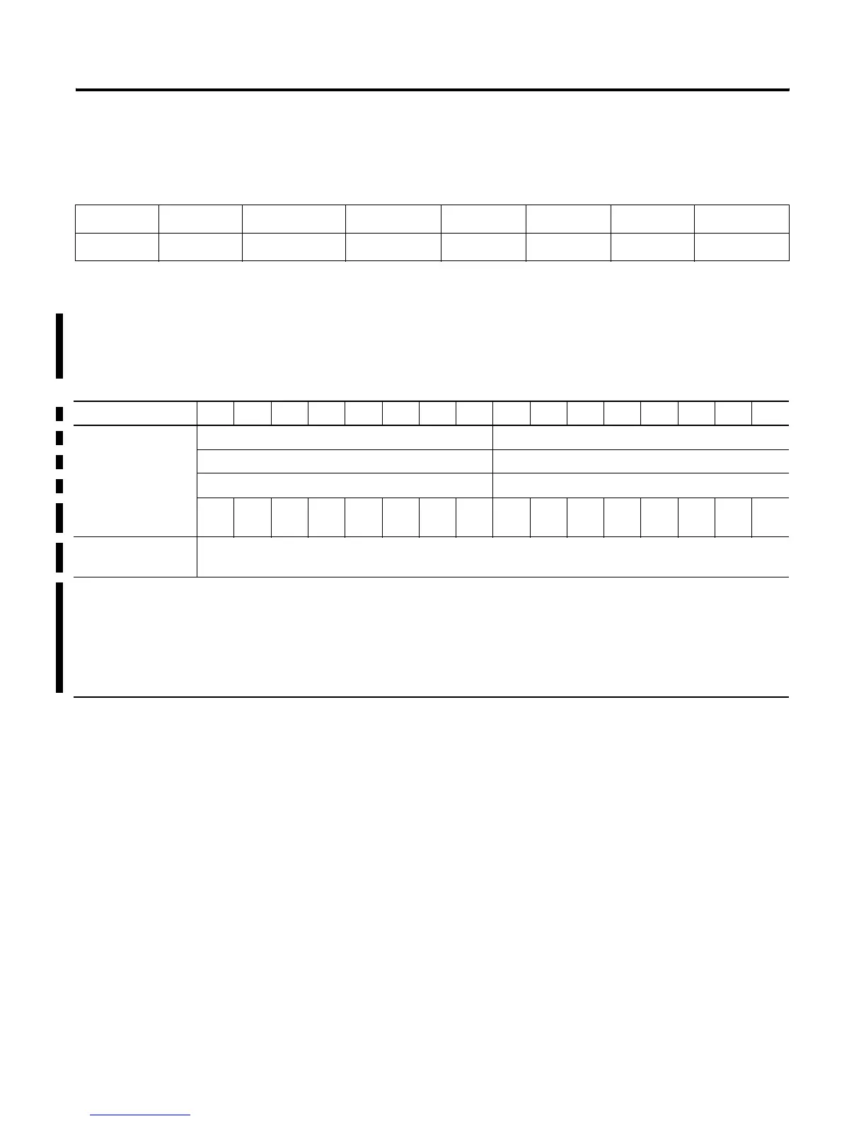
1734-IE2V Analog Input Module
Message size: 6 Bytes
Table D.A
Channel Status Byte
Bit 7 Bit 6 Bit 5 Bit 4 Bit 3 Bit 2 Bit 1 Bit 0
Over Range Under Range High High Alarm Low Low Alarm High Alarm Low Alarm CAL Mode Channel Fault
15 14 13 12 11 10 09 08 07 06 05 04 03 02 01 00
Produces (scanner Rx) Input Channel 0 - High Byte Input Channel 0 - Low Byte
Input Channel 1 - High Byte Input Channel 1 - Low Byte
Status Byte for Channel 1 Status Byte for Channel 0
OR UR HHA L
LA
HA LA CM CF OR UR HHA L
LA
HA LA CM
CF
Consumes (scanner
Tx)
No consumed data
Where: CF = Channel Fault status; 0 = no error, 1 = fault
CM = Calibration Mode; 0 = normal, 1 = calibration mode
LA = Low Alarm; 0 = no error, 1 = fault
HA = High Alarm; 0 = no error, 1 = fault
LLA = Low/Low Alarm; 0 = no error, 1 = fault
HHA = High/High Alarm; 0 = no error, 1 = fault
UR = Underrange; 0 = no error, 1 = fault
OR = Overrange; 0 = no error, 1 = fault

 Loading...


