Publication 1734-UM002C-EN-P - July 2003
D-6 Default Data Maps
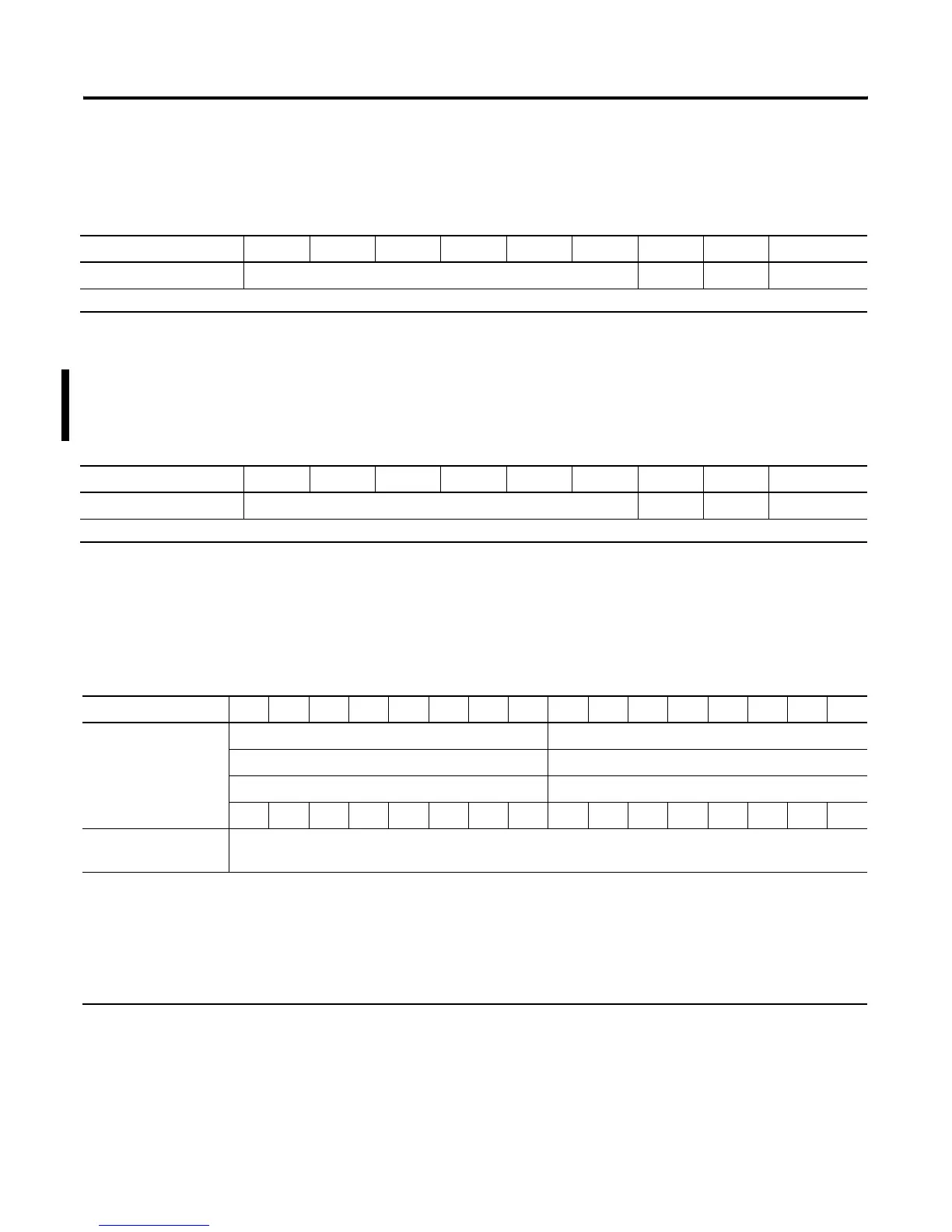
1734-OW2 Relay Sink/Source Output Module
Message size: 1 Byte
1734-OX2 Relay Output Module
Message size: 1 Byte
1734-IE2C Analog Current Input Module
Message size: 6 Bytes
7 6 5 4 3 2 1 0
Consumes (scanner Tx) Not used Ch1 Ch0 Channel state
Where: 0 = OFF 1 = ON
7 6 5 4 3 2 1 0
Consumes (scanner Tx) Not used Ch1 Ch0 Channel state
Where: 0 = NO contact OFF, NC contact ON1 = NO contact ON, NC contact OFF
15 14 13 12 11 10 09 08 07 06 05 04 03 02 01 00
Produces (scanner Rx) Input Channel 0 High Byte Input Channel 0 Low Byte
Input Channel 1 High Byte Input Channel 1 Low Byte
Status Byte for Channel 1 Status Byte for Channel 0
OR UR HHA LLA HA LA CM CF OR UR HHA LLA HA LA CM CF
Consumes
(scanner Tx)
No consumed data
Where: CF = Channel Fault status0 = no error1 = fault
CM = Calibration Mode0 = normal1 = calibration mode
LA = Low Alarm0 = no error1 = fault
HA = High Alarm0 = no error1 = fault
LLA = Low/Low Alarm0 = no error1 = fault
HHA = High/High Alarm0 = no error1 = fault
UN = Underrange0 = no error1 = fault
OR = Overrange0 = no error1 = fault

 Loading...


