Publication 1734-UM002C-EN-P - July 2003
D-12 Default Data Maps
1734-VHSC 5V dc High Speed Counter Module
Message size: 6 Bytes
1734-SSI Synchronous Serial Interface Absolute
Encoder Module
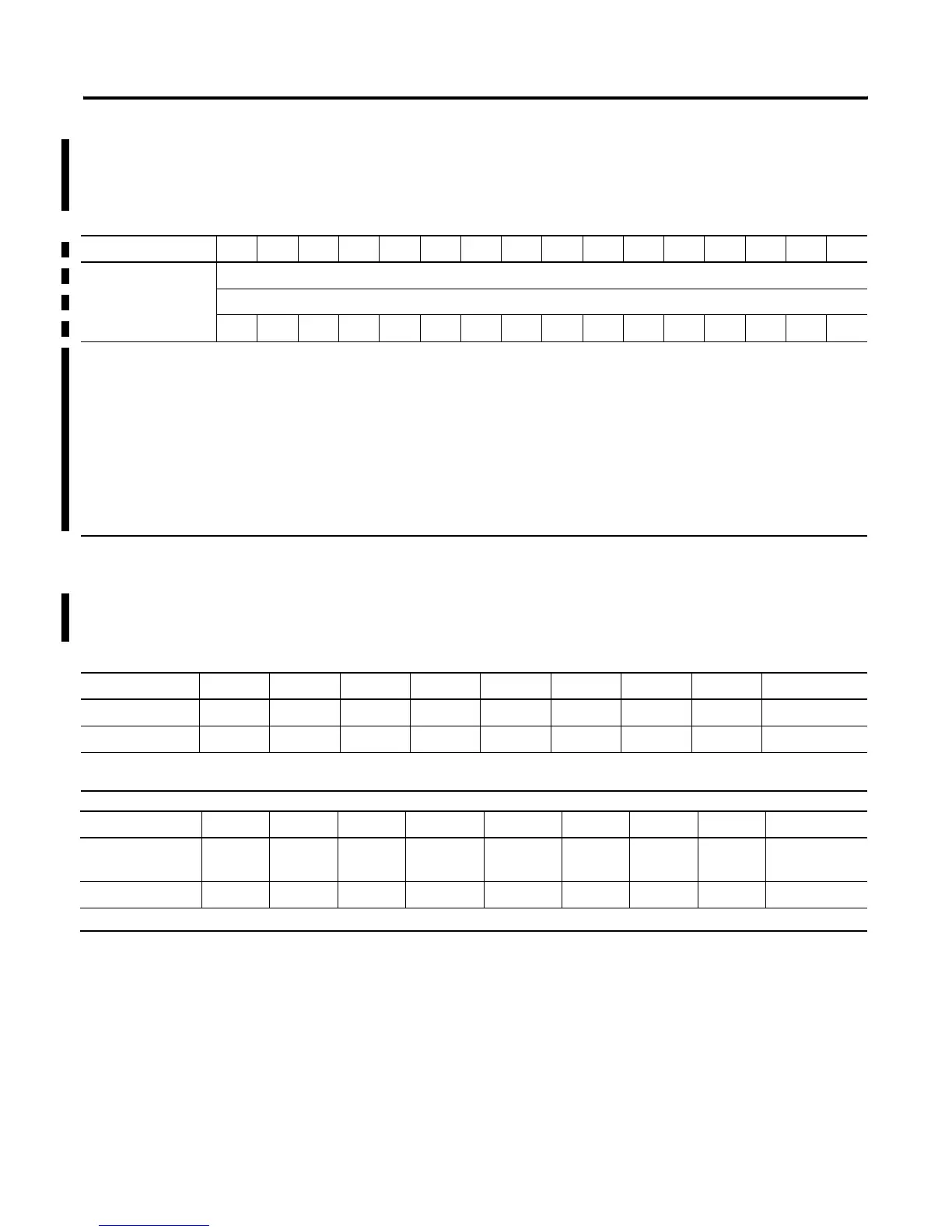
15 14 13 12 11 10 09 08 07 06 05 04 03 02 01 00
Produces (scanner Rx) Channel 0 value of present counter state (LSW)
Channel 0 value of present counter state (MSW)
PE EF NR 0 FS FS OS OS 0 ZS BS AS C1 C0 ZD 0
Where: PE = Programming error
EF = EEPROM fault status
NR = Not ready status bit
FS = Output fault status bit - bit 10 for output 0, bit 11 for output 1
OS = Output on/off status bit - bit 8 for output 0, bit 9 for output 1
ZS = Z input status
BS = B input status
AS = A input status
C = Stored data count
ZD = Zero frequency detected
LSW = Least significant word
MSW = Most significant word
7 6 5 4 3 2 1 0
Produce 8 C2ST
C1ST C2R C1R INC DEC
RUN I1 Status Byte 0
1
Produce 9 RES
RES RES LHON
IDF
2
CCE
CCF SPF Status Byte 1
1
1. For detailed descriptions of these bits, see 1734-SSI User Manual, publication 1734-UM009.
2. Monitor IDF to determine the validity of the produced data. If IDF=1, the SSI data is false.
7 6 5 4 3 2 1 0
Consume 0 RES
RES RES SCMP2 SCMP1 CC2
CC1 LACK Master ACK
Byte
1
Consume 1 RES
RES RES RES RES RES
RES RES CONS1
3. The master must provide the Master ACK Byte in order to receive the polled Produced bytes 0-9.

 Loading...


