Publication 1734-UM002C-EN-P - July 2003
B-18 1734-ADNX Quick Start
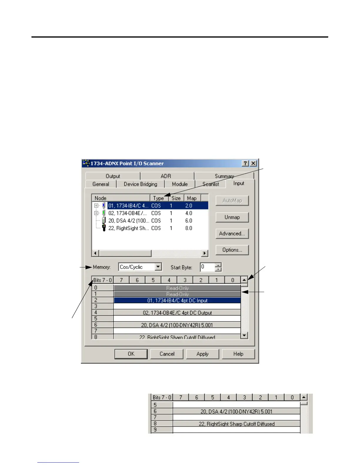
Inputs and Outputs
1. Select the Input tab. A single word is 16 bits. Notice that the
mapping is as expected.
• The first two bytes (1 byte = 8 bits) are reserved as read only.
• The first word is completely used, so the 1734-IB4 can map to
the beginning of the next word (Byte 2, bit 0).
• There is a space between the 1734-IB4 and the 1734-OB4E
because the next word does not start until Byte 4. The same is
true for the DSA and the RightSight.
Scroll down and notice that bytes 0 through 8 = 9 bytes total
were enough for the input data.
This field describes how the
data is transferred between
the I/O modules and the
adapter on the PointBus
Subnet.
The first 2 bytes are
reserved for status.
Use the scroll bar as
needed to see all of the
data.
The current memory
buffer selected is
COS/Cyclic. There are
also buffers for Polled
and Strobed. This is
how the data will be
transferred to the
scanner (1756-DNB in
this example).
Note the mapping in
the 1734-ADNX
Scanner is shown in
byte increments. The
1756-DNB displays in
double words (4 bytes).

 Loading...


